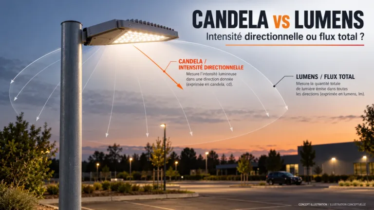







Power factor (PF) is real power divided by apparent power in an AC circuit. Real input power is measured in watts (W); apparent power is measured in volt-amperes (VA). A PF of 0.95 means 95 W of real power for every 100 VA of apparent power at that operating point. It does not mean the driver converts 95% of its input into useful LED output.
For a street-light or parking project, the practical issue is not whether one catalogue prints a bigger PF number. It is whether the quoted electrical performance applies to the driver, LED load, supply voltage and dimming scene you will actually use. A full-output result can leave an important part of the nightly operating schedule unanswered.

Power factor formula: keep W and VA separate
For a single-phase AC input, PF = P ÷ S, with apparent power S = V RMS × I RMS. Therefore, I RMS = P ÷ (V RMS × PF). Use real input watts, not the LED output rating. Using W and VA gives a dimensionless ratio; using kW and kVA gives the same ratio if both use the same scale. The Fluke power-factor guide explains the real-to-apparent-power relationship.
RMS means root mean square, often called the effective voltage or current. Multiplying volts by amperes gives VA, not automatically real watts for an AC LED load. For electronic drivers, request true power factor rather than assuming that a phase-angle-only value tells the whole story. Do not use a three-phase line-voltage calculation interchangeably with this single-phase example.
Same 100 W, different input current
Consider two fictional loads drawing the same 100 W of real input power from a 230 V single-phase AC supply. Their power factors are 0.95 and 0.80. The following arithmetic is a teaching comparison, not Inlux model data, a product test or a circuit-design recommendation.
| Illustrative AC input | Real input power (W) | True input PF | Apparent power | Steady-state current |
|---|---|---|---|---|
| Example A | 100 W | 0.95 | 100 ÷ 0.95 ≈ 105.3 VA | 100 ÷ (230 × 0.95) ≈ 0.458 A |
| Example B | 100 W | 0.80 | 100 ÷ 0.80 = 125.0 VA | 100 ÷ (230 × 0.80) ≈ 0.543 A |
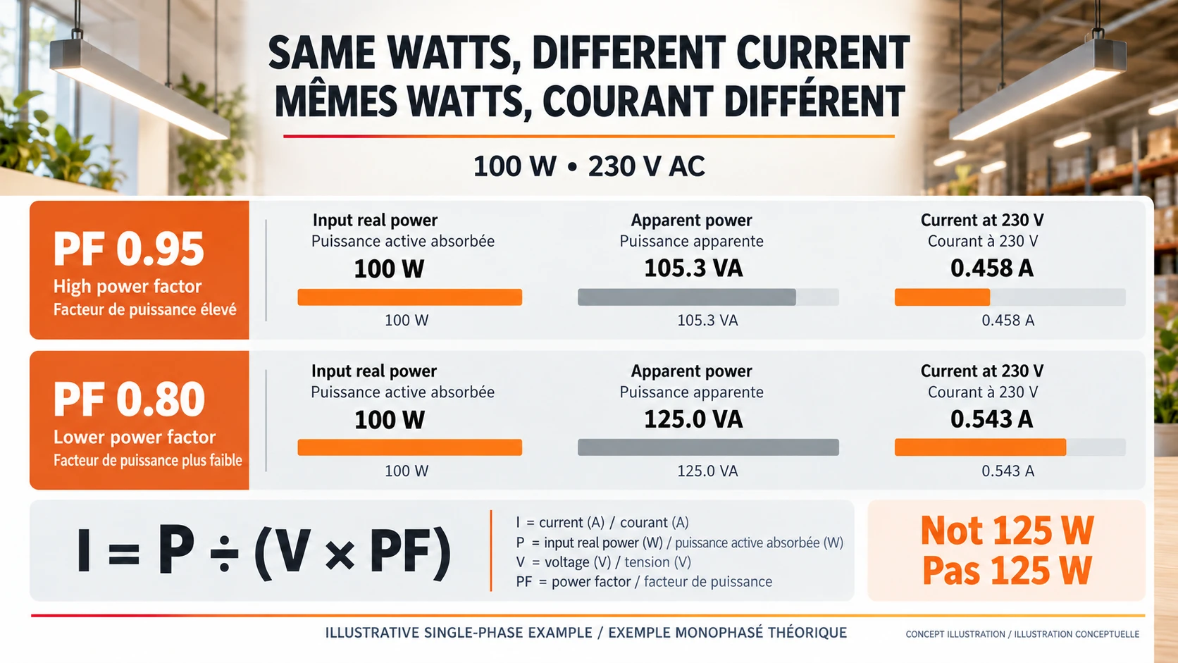
Example B needs more apparent power and current at the same real input watts. It does not consume 125 W simply because its apparent power is 125 VA. Nor does PF 0.80 prove that 20% of energy is wasted as heat. Driver conversion losses are already part of its real input power and must be assessed using the separate efficiency figure.
The difference can matter when many lights share an AC supply. But do not multiply this table into a cable, breaker or generator specification. Starting current, harmonic currents, phase allocation, voltage drop, ambient conditions and the applicable installation rules still require a qualified electrical design. The table compares steady-state inputs only.
Five checks before accepting an LED power-factor claim
1. Read the conditions beside the headline rating
A statement such as “PF above 0.95” is incomplete without its test conditions. Identify the supply voltage and frequency, driver variant, LED load, output setting and measurement basis. Distinguish a typical value from a guaranteed minimum. A result measured at one voltage and full load does not automatically establish the same result at another voltage or at a lightly loaded setting.
2. Include the dimmed part of the night
A road luminaire may spend much of the night below maximum output. Ask for electrical results at the relevant dimming states rather than carrying the full-load PF across the whole schedule. In its LED power-supply FAQ, MEAN WELL explains that output load and LED forward-voltage conditions affect PF and that model-specific load requirements must be checked. Its examples are not universal operating limits for other drivers.
| Supply condition to review | Lighting state to review | Record together | Procurement question |
|---|---|---|---|
| Nominal project AC voltage | Maximum specified output | Input W, RMS A, true PF and current THD | Does the quoted rating match this configuration? |
| Nominal project AC voltage | Scheduled dimmed output | Same electrical fields plus actual dimming command | Is part-load performance documented? |
| Relevant low-end AC operating condition | Maximum specified output | Same fields, with voltage and frequency recorded | Does the requirement still apply at this input? |
| Relevant low-end AC operating condition | Scheduled dimmed output | Same fields and any operating limitations | Is this combination within the approved envelope? |
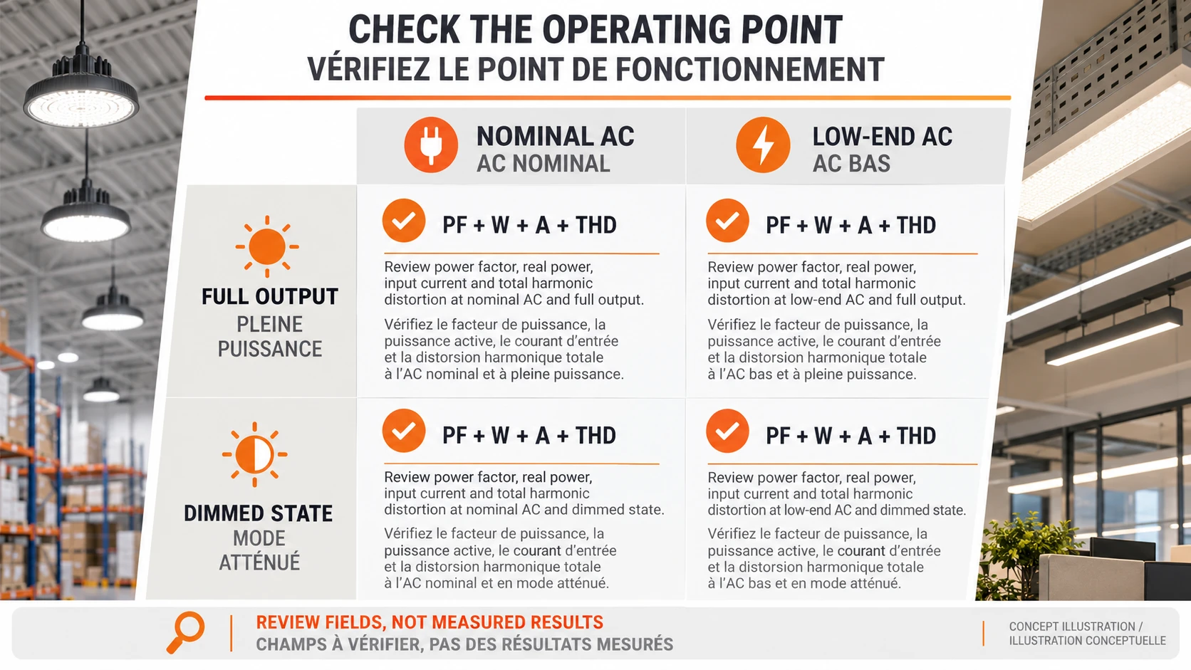
This matrix is a proposal for a useful evidence request, not a mandatory test standard or permission to operate outside the nameplate range. Choose the actual project conditions with the supplier and electrical designer. A dimming command expressed as a percentage is not, by itself, a measurement of input watts, light output or PF.
3. Keep PF, efficiency and THD in different columns
Power factor concerns the AC input power relationship. Driver efficiency compares output power with real input power. Current THD describes harmonic distortion of the input current; it is not the same test as PF. Luminous efficacy, in lm/W, concerns light output per electrical watt. The Texas Instruments LED power-supply overview treats efficiency, PF and THD as separate design criteria. One attractive number does not qualify the other columns.
If a specification requests both PF and a current-harmonic limit, request both results on a compatible measurement basis. Do not treat a supplier’s high PF as proof of a particular THD percentage, flicker performance, surge immunity or EMC compliance. Those are separate requirements, each with its own scope and evidence.
4. Use the input watts for supply-side comparisons
A “100 W LED module” is not necessarily a luminaire drawing 100 W from the mains. Compare complete-luminaire input power at the quoted operating state, including the driver and relevant controls. For the actual current calculation, use our watts-to-amps calculator. For output-current and voltage matching, use the separate LED driver selection guide; do not substitute PF for that compatibility check.
5. Separate a billing claim from an energy claim
A higher PF is not a promise of a particular reduction in billed kWh. Ask which tariff applies: charges for real energy, apparent-power demand or reactive energy are not interchangeable. Whether a PF-related charge applies depends on the supply contract and local rules. Any savings forecast should state that tariff and the measured operating baseline, rather than assuming a universal penalty threshold or percentage saving.
Where the AC boundary ends in solar street lighting
A purely battery-fed DC light does not use AC power factor as its battery-sizing input. Its electrical review needs battery voltage, real power, conversion losses and energy over time. Do not divide the nightly DC watt-hours by an AC PF number to enlarge or shrink the battery requirement. For a hybrid system with a separate AC charger or AC-powered path, assess PF at that AC input—not at the DC LED output.
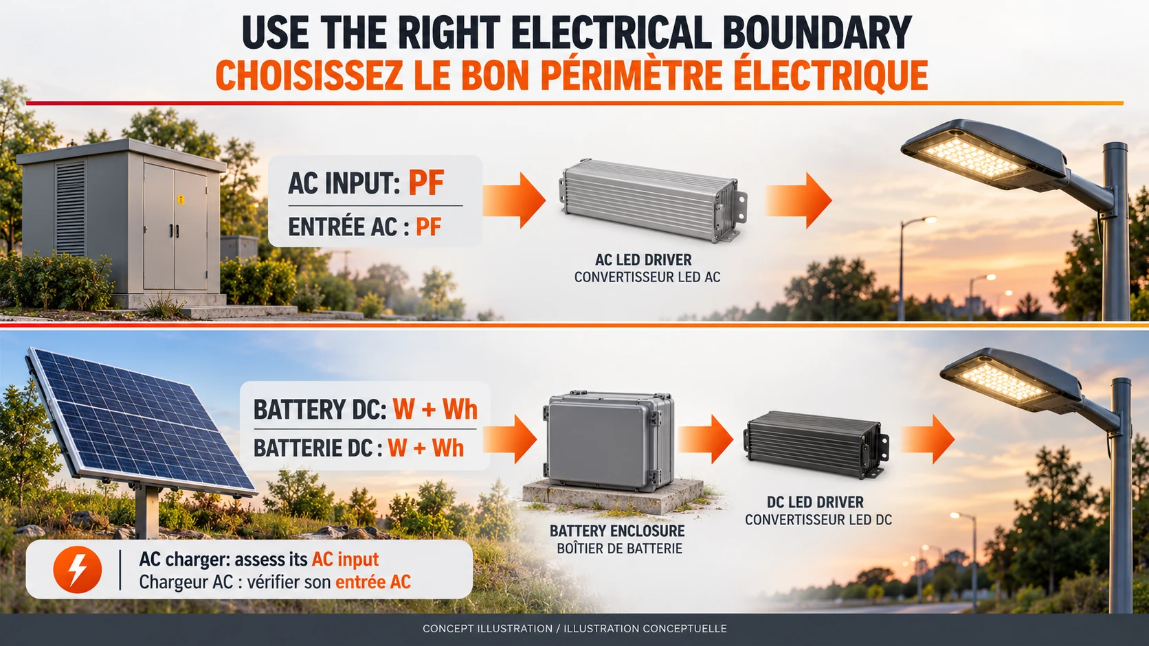
This is why an AC LED street light range and an off-grid solar street light product range need different supply-side questions. Compare the Inlux All-in-One range dan the Inlux All-in-Two range on their actual system architecture. Housing format alone does not establish an AC power-factor rating.
Pertanyaan yang sering diajukan
What does a 0.95 power factor mean?
It means real power is 0.95 times apparent power at that operating point. A load drawing 100 W therefore has about 105.3 VA of apparent power. It does not establish 95% driver efficiency, a particular lumen output or performance at every dimming level.
Does 0.8 or 80% PF mean 20% of the energy is wasted?
No. It expresses the ratio of real to apparent power, not a conversion-efficiency percentage. At 100 W input and PF 0.8, apparent power is 125 VA. Real energy use must be evaluated from real watts over time; the VA figure is not substituted for watts.
What is a good power factor for LED street lights?
Use the project’s actual requirement, with its voltage, load and dimming conditions. Values close to unity can be desirable, but a full-load typical value is not a universal guaranteed minimum. Confirm the complete luminaire’s applicable evidence rather than accepting an unqualified catalogue number.
Does dimming always improve power factor?
No. PF can change with load, supply voltage, driver design and operating mode. A lower input-watt reading alone does not prove a higher PF. Review results for the actual dimming scenes and do not extend a model-specific full-load result to every scene.
Does a high PF prove low THD or flicker-free light?
Not on its own. Current THD, output ripple, flicker and electrical compatibility have separate definitions and evidence. Keep the requested results distinct in the submittal and confirm that each applies to the offered configuration and operating conditions.
Does an off-grid solar street light need AC PFC?
A purely battery-DC lighting path is not selected using an AC PF rating. If the system includes an AC charger or AC supply path, review that equipment’s AC input separately. Do not add capacitors or modify a driver to “correct PF” without an approved design; this guide is not a wiring or retrofit procedure.
Send a supply-aware lighting brief
Inlux Solar serves projects in 60+ countries, where supply arrangements and procurement requirements differ. For a road or commercial solar parking lot lighting enquiry, state the country, AC or off-grid supply, required operating schedule and project criteria. Then send Inlux Solar your project enquiry. Ask for a comparable configuration and clearly identify which electrical claims still need confirmation; do not use this guide’s example values as product guarantees.