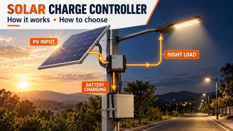







Jawaban cepat: The best solar panel angle is the fixed tilt and compass direction that gives a project enough usable energy during its hardest operating period—not simply the angle that produces the most annual energy. Latitude is a useful first estimate, but the final choice should compare site solar data, seasonal load, shadows, module temperature, drainage, cleaning access, wind loading and the adjustment limits of the actual bracket.
For a solar street light, the question is especially practical. The panel has to replace the energy used by the LED every night and recover the battery after weak-sun days. A theoretically perfect annual angle can still fail if trees shade the panel in the rainy season, a road forces the panel toward the wrong azimuth, or an integrated luminaire couples panel tilt to the light distribution.
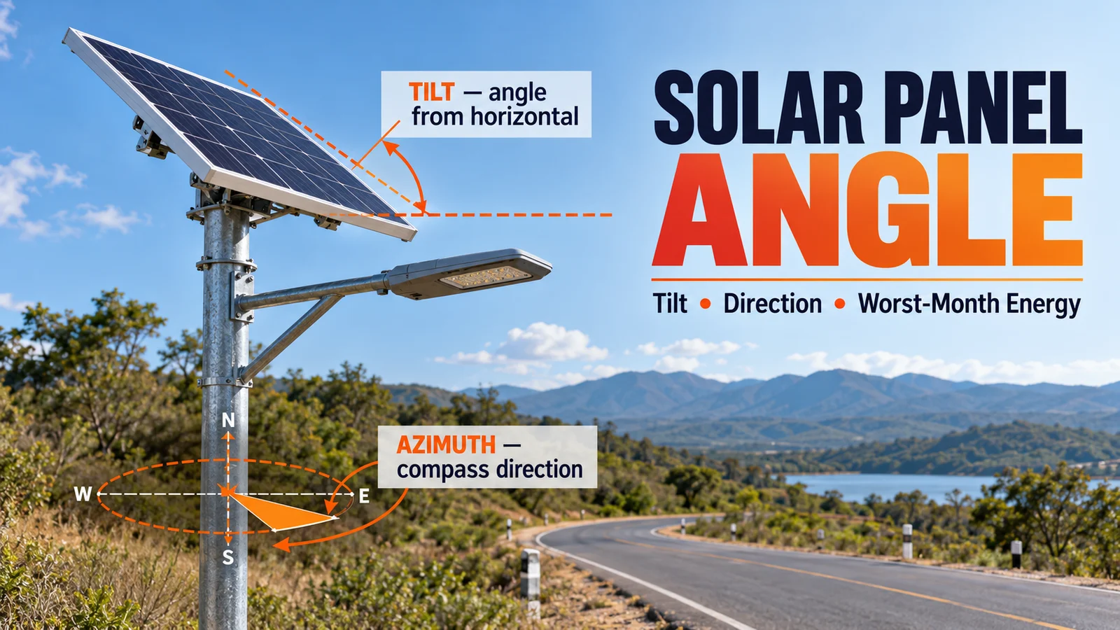
Solar panel angle has two coordinates
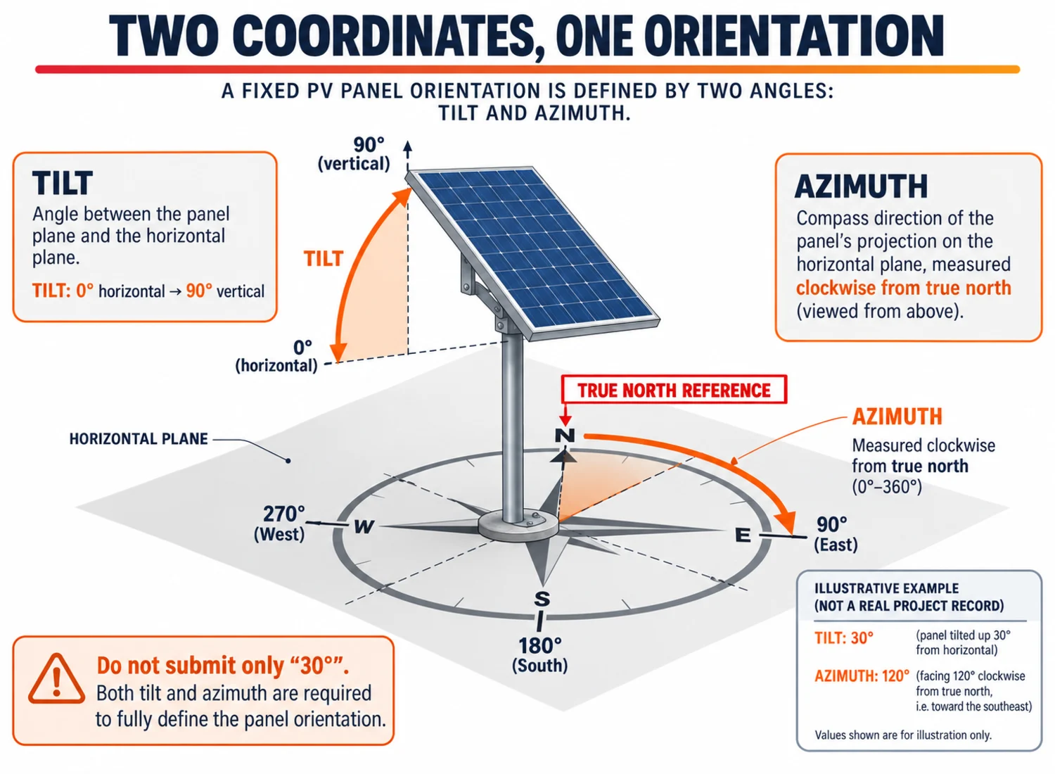
“Angle” is often used as if it were one setting. A fixed PV module actually needs two orientation values:
- Tilt: the angle between the module surface and horizontal. A horizontal panel is 0°; a vertical panel is 90°.
- Azimuth: the compass direction the module faces. The convention must be stated because some software uses degrees clockwise from north while other documents use a different reference.
Sandia National Laboratories’ PV Performance Modeling Collaborative treats array orientation as an input to PV performance calculations and describes it using tilt and azimuth vectors. That distinction prevents a common installation error: specifying “30 degrees” without recording which direction the raised edge faces.
Use this field notation:
Tilt: ___° from horizontal | Azimuth: ___° using [named convention] | Reference: true north
The reference matters. A phone or handheld compass may indicate magnetic north, while a drawing or solar model normally needs true direction. NOAA’s World Magnetic Model provides the geomagnetic declination framework used to relate magnetic variation to geographic direction. Record the tool, date and correction used; do not tell an installer only to “point it south.”
Is latitude the best solar panel angle?
Setting fixed tilt close to site latitude is a common annual-energy starting point. It is not a universal design answer. The rule does not know:
- which months have the lowest solar resource;
- whether the nightly lighting schedule changes by season;
- whether the project prioritizes annual energy or worst-month reliability;
- how much diffuse radiation is present in cloudy periods;
- where nearby trees, buildings, poles or hills block the sun;
- whether soiling, rain runoff or standing water impose a minimum tilt;
- which angles the bracket and structure can safely support.
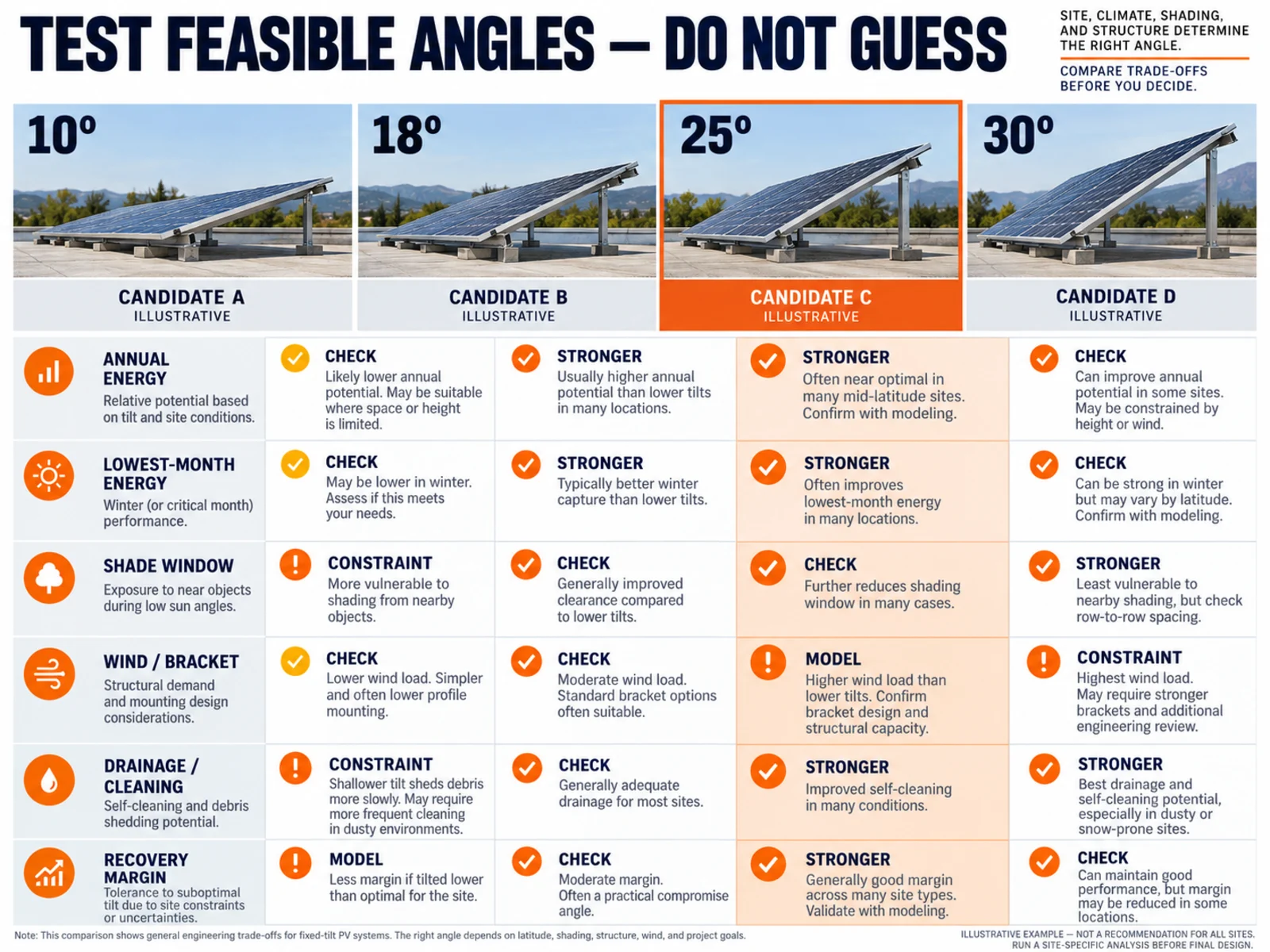
A better workflow tests a short list of feasible orientations. For example, a fictional site at 18° latitude might compare 10°, 18°, 25° and 30° tilt—not because one of those is automatically correct, but because they bracket a practical range. Model monthly energy for each option, apply the same system losses and load schedule, then compare the lowest-energy month and battery recovery time.
Do not publish a “latitude plus 15° in winter” or “latitude minus 15° in summer” shortcut as a guaranteed street-light setting. Seasonal adjustment may be useful for accessible ground arrays, but most municipal street-light panels are fixed after commissioning. A setting that requires technicians to revisit every pole is not a fixed-angle design.
Choose the objective before choosing the angle
Three projects at the same coordinates can need different decisions.
| Design objective | What to optimize | Typical conflict |
|---|---|---|
| Highest annual PV energy | Total modeled energy over 12 months | May underperform in the critical low-resource month |
| Strongest worst-month energy | Minimum monthly plane-of-array energy | May sacrifice some annual total |
| Fast battery recovery | Energy surplus after the nightly load | Depends on battery limits and controller current |
| Lower cleaning burden | Drainage, natural wash-off and safe access | Steeper tilt may increase wind load |
| Low structural demand | Wind area, bracket leverage and pole loading | Flatter or integrated layouts may reduce energy or drainage |
| Site-fit and anti-shading | Clear solar window around obstacles | Best compass direction may be physically unavailable |
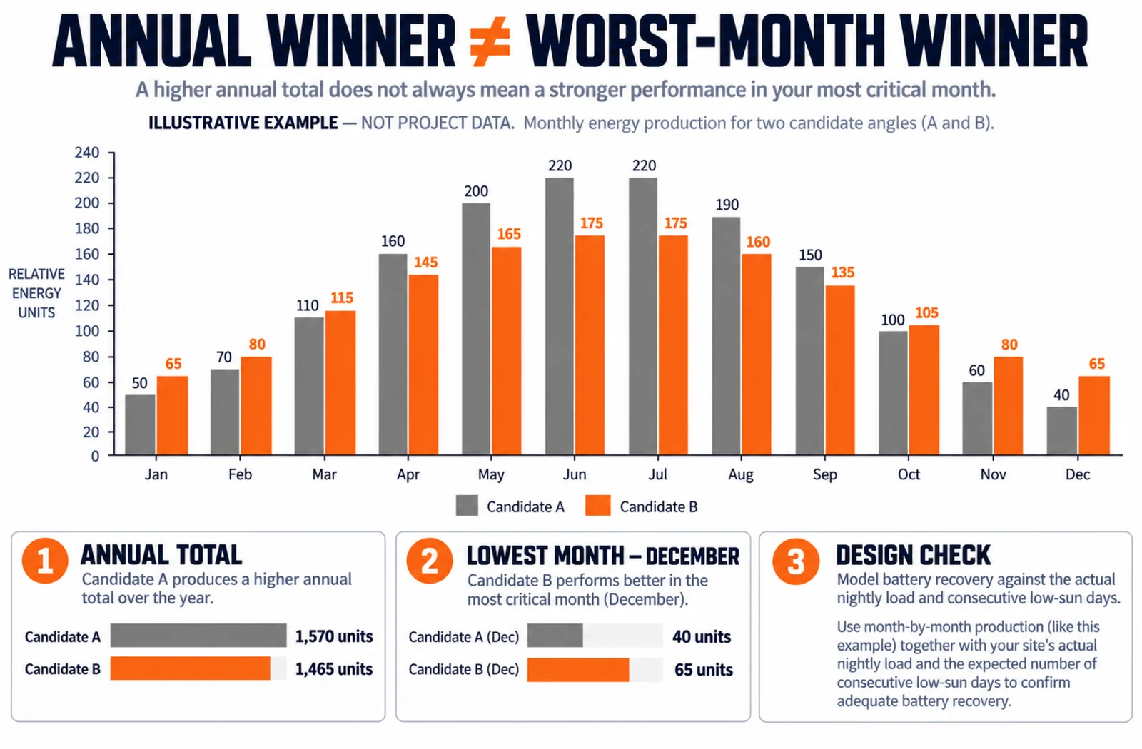
Solar street lights normally deserve a worst-month view. The worst-month peak sun hours guide explains why an annual average can hide the period that drives autonomy. The panel angle should be evaluated with the same weather period and operating schedule used for solar street-light battery sizing.
A project method for choosing solar panel tilt and direction
1. Fix the site coordinates and design period
Record latitude, longitude, elevation where relevant and the months that define the design case. A city name alone can be too broad for a large region. Use the exact road, parking area or project corridor coordinates.
Solar-resource tools are inputs, not guarantees. NASA POWER’s Data Access Viewer and the World Bank Group/ESMAP Global Solar Atlas can support early-stage screening. For final design, record the dataset, period, spatial resolution, irradiation variable and any ground measurement used. Do not mix horizontal irradiation from one source with plane-of-array output from another without documenting the conversion.
2. Define the nightly energy schedule
The panel does not serve a generic “lamp wattage.” It serves an operating schedule. A fictional 60 W luminaire running four hours at 100%, six hours at 50% and two hours at 30% has an LED energy schedule of:
(60 W × 4 h) + (30 W × 6 h) + (18 W × 2 h) = 456 Wh/night
Controller self-consumption, driver losses, battery charge/discharge losses, wiring losses and reserve sit outside that LED-only number. If motion sensing is used, state the guaranteed base profile and the assumed trigger allowance separately. The day-to-night solar-light system guide shows why charging logic, stored energy and the lighting load belong in the same record.
3. Map the solar window, not just the horizon
Visit the site or obtain a defensible obstruction survey. Record shadows at multiple times and in the critical season. One midday photograph cannot reveal morning and afternoon shading. Trees may also change with growth or leaf condition.
For each candidate pole, check:
- clear sky window across the main charging period;
- nearby buildings, signs, cables and other poles;
- current and future tree canopy;
- terrain or ridge obstruction;
- self-shading from the luminaire, arm, battery box or second panel;
- row-to-row shading where several modules share a structure;
- dust, bird activity and local maintenance constraints.
The direct sunlight guide explains the difference between a bright day and unshaded direct exposure. Shading should be represented as a time-dependent loss, not a single guess such as “10% shade.”
4. Generate feasible tilt and azimuth options
Start with the energy-oriented candidates, then remove orientations the actual hardware cannot achieve. A fixed bracket may offer discrete holes rather than continuous adjustment. An all-in-one light may have a narrower range because the PV surface and luminaire body share one assembly. All-in-two and split systems can give more independent panel placement.
The All-In-Two Solar Street Light page describes that flexible PV orientation as a system feature. The Split Type Solar Street Light page covers configurations where the panel, luminaire and battery arrangement are more separated. Do not promise any tilt range until the exact bracket drawing is confirmed.
5. Model monthly plane-of-array energy
The useful result is not only global horizontal irradiation. The model should convert the solar resource to the candidate panel plane and account for module, temperature, wiring, mismatch, controller and battery-related losses appropriate to the design stage.
A screening calculation can be written as:
Estimated daily PV energy ≈ module rating (Wp) × plane-of-array peak-sun-hours × documented derating factor
If a fictional 180 Wp module receives 4.2 plane-of-array peak-sun-hours and the declared screening derating is 0.72:
180 Wp × 4.2 h × 0.72 ≈ 544 Wh/day
That is an instructional calculation, not an Inlux configuration and not proof of autonomy. It must be compared with the complete nightly load, usable battery energy, recovery requirement and low-resource sequence. A single average day also does not represent several consecutive weak days.
6. Compare the limiting month and recovery margin
Build one row per orientation and one column per month. Highlight the minimum modeled energy, not just the annual total. Then calculate the monthly surplus after the same system load and losses.
| Candidate | Annual energy index | Lowest-month energy | Shade exposure | Structural/maintenance note | Decision |
|---|---|---|---|---|---|
| A: lower tilt | 100 | 82 | Clear morning; partial late-afternoon shade | Better wind profile; weaker runoff | Keep for comparison |
| B: mid tilt | 99 | 88 | Clear main solar window | Bracket standard position | Preferred screening option |
| C: steeper tilt | 96 | 90 | Clear | Higher wind moment; easier runoff | Structural review required |
The numbers above are fictional indices, not a site recommendation. Their purpose is to show why the annual winner and worst-month winner can differ.
7. Apply structural, drainage and service constraints
Changing tilt changes more than energy. It changes the projected area seen by wind, the load path through the bracket, fasteners and pole, the chance of water or dirt remaining on the surface and the reach needed for cleaning. The final orientation must be included in the structural design case—not adjusted casually in the field after the pole and foundation were approved.
Permintaan:
- panel and bracket drawing with permissible angles;
- fastener grades, torque and locking method;
- wind design basis and orientation used in the calculation;
- pole, arm and foundation compatibility;
- cable bend radius, drip loop and connector support at every angle;
- anti-theft details where required;
- cleaning method and safe access;
- corrosion system for the site environment.
The solar street-light installation guide covers the broader foundation, lifting and commissioning sequence. Panel aiming should be signed off before final torque marks and photographs are recorded.
8. Freeze the selected configuration
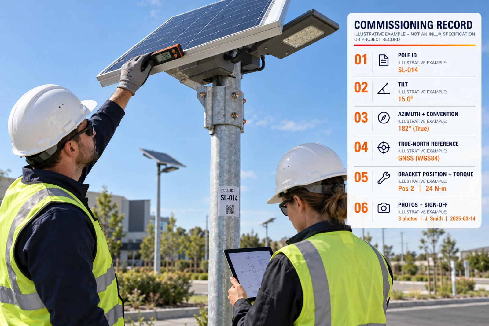
The approved drawing should state panel model, quantity, portrait/landscape orientation, tilt, azimuth convention, true-direction reference, bracket position, fastener torque, cable route and acceptable field tolerance. If multiple pole orientations are needed along a curved road, list each pole or repeatable group.
Do not leave the contractor to select the angle from a catalogue photograph. A finished commissioning record makes later diagnosis possible when one light underperforms while neighboring lights do not.
Solar street-light panel angle is not luminaire angle
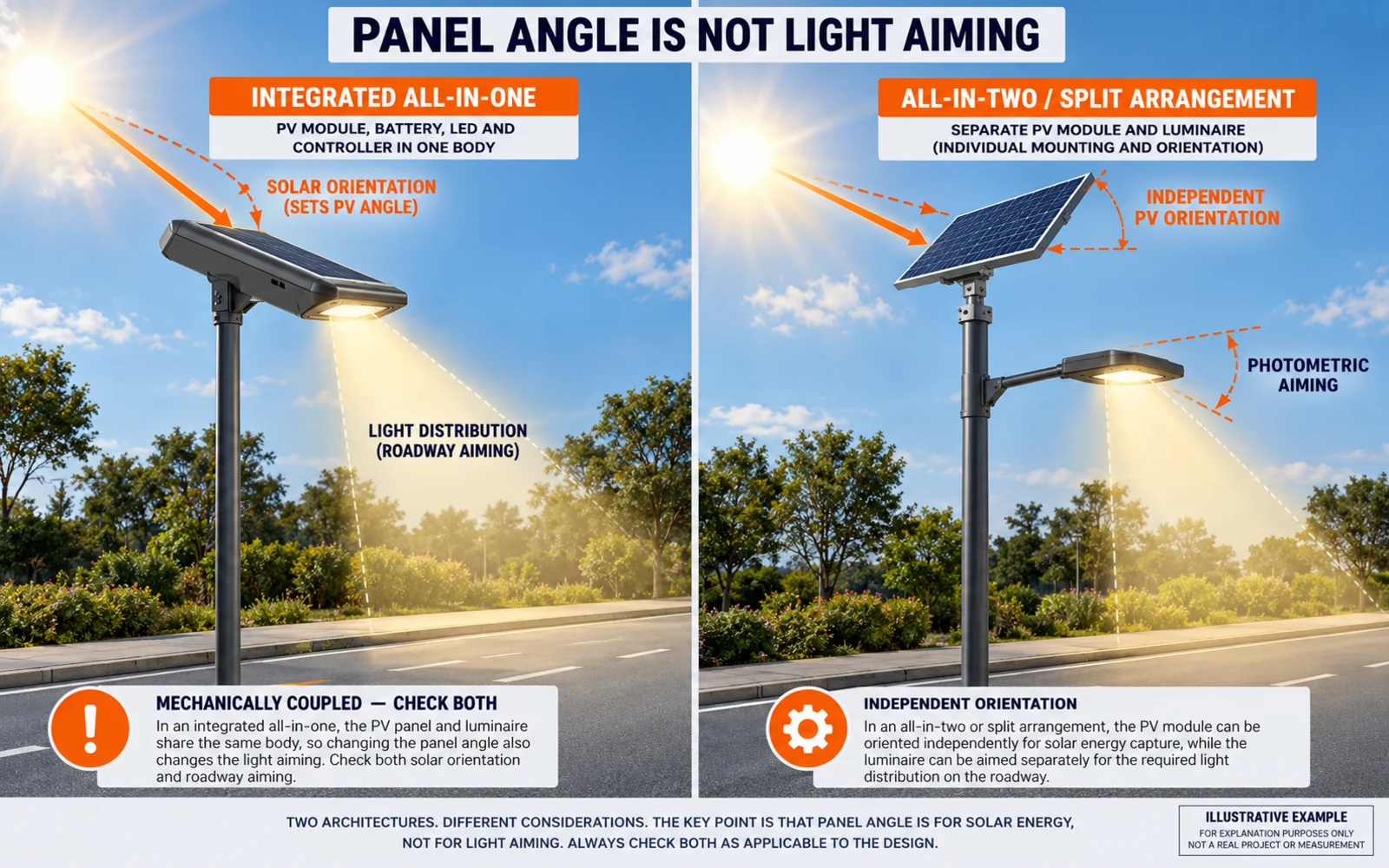
The PV module collects energy; the luminaire distributes light. Tilting the luminaire to improve road coverage is a photometric decision. Tilting the panel is an energy and structural decision. In an integrated product, those two functions may be mechanically linked, which creates a design trade-off.
Never rotate a complete all-in-one unit solely to face the panel toward the sun if that rotation sends the optical distribution away from the road or increases glare. Confirm the allowed adjustment in the product drawing and validate the resulting lighting layout. Where independent control is necessary, an all-in-two or split arrangement may be more appropriate.
Common solar panel angle mistakes
Copying one angle to every country
Latitude, seasonal solar path, cloud pattern, load schedule and obstruction differ. A catalogue’s demonstration angle is not a global standard.
Using annual irradiation for an autonomy claim
An annual total can look strong while a rainy or winter month has an energy deficit. Use the same critical period throughout panel, battery and control calculations.
Confusing true and magnetic direction
Record the azimuth convention and direction reference. A compass screenshot without correction, date or location is not an auditable installation record.
Ignoring diffuse light and local shade
Cloudy-sky energy and time-dependent shade can change the relative result between candidate orientations. Model the actual solar window rather than assuming every lost hour has the same effect.
Adjusting the bracket after structural approval
A steeper module can increase wind effects and bracket leverage. Treat orientation as part of the approved mechanical configuration.
Optimizing the panel while damaging light distribution
Integrated systems can couple panel and luminaire orientation. Energy collection and photometric aiming must both pass.
Reporting only the final number
“Tilt 20°” is not reproducible without the site, dataset, azimuth, design month, losses, shade model, bracket drawing and tolerance.
Copy-paste solar panel orientation schedule
Use this table in a submittal or commissioning sheet. Add project-specific fields rather than deleting evidence columns.
| Field | Required record |
|---|---|
| Asset | Pole ID, coordinates, road/area and drawing reference |
| Modul PV | Manufacturer, model, quantity, Wp and serial/batch link |
| Orientation | Tilt from horizontal, azimuth convention and true-direction reference |
| Design case | Critical month, nightly load profile and autonomy target |
| Solar source | Dataset/tool, period, variable, resolution and retrieval date |
| Shade | Survey method, obstruction record and critical-season assumption |
| Losses | Temperature, soiling, wiring, mismatch, controller and battery assumptions |
| Mekanis | Bracket position, wind basis, fasteners, torque and corrosion protection |
| Listrik | Cable route, connectors, polarity, Voc/current checks and controller settings |
| Penerimaan | Inclinometer reading, direction reading, photos, torque marks and sign-off |
Inlux Solar has delivered more than 300,000 lighting units across 60+ countries. That range is why the project record should be site-specific rather than built around one global tilt rule. For a complete quotation, send coordinates, pole layout, mounting constraints, nightly schedule, autonomy requirement, quantity and the applicable wind/environmental criteria through the project enquiry page.
Pertanyaan yang Sering Diajukan
What is the best solar panel angle?
There is no single best angle for every project. A fixed panel often starts with a latitude-based screening value, then compares feasible tilt and direction options using monthly plane-of-array energy, the critical load period, shadows, losses and the approved bracket. For a solar street light, the preferred option is normally the one that supports the required worst-month energy and recovery margin.
Should solar panels always face south?
Not everywhere and not without defining the reference. Equator-facing orientation is a common annual-energy starting point—generally south-facing in the northern hemisphere and north-facing in the southern hemisphere—but local shade, seasonal objectives and mounting constraints can change the preferred azimuth. Record true direction and the software convention used.
Is a 0-degree flat solar panel acceptable?
A horizontal panel can collect energy, especially near the equator, but it may have poorer drainage and soiling behavior and may not maximize the project’s critical-period energy. Check modeled output, rainfall, dust, ponding risk, cleaning access and the module/bracket documentation before approving a flat arrangement.
Does changing solar panel tilt improve winter output?
A steeper fixed tilt can increase collection in some low-sun periods, but the result depends on latitude, weather, diffuse radiation, azimuth and shade. Compare monthly modeled energy rather than applying a fixed seasonal shortcut. Also verify wind loading and the bracket’s approved positions.
How accurately must installers set the angle?
The designer should state an allowable tolerance based on model sensitivity and hardware adjustment increments. Commissioning should record the measuring tool, tilt, azimuth reference, pole ID, photographs and fastener torque. Precision beyond the accuracy of the bracket, compass correction and site model is not useful.
Can I change an all-in-one street light angle to aim the panel?
Only within the manufacturer’s approved adjustment method and after checking light distribution. On an integrated unit, rotating or tilting the body can change both solar collection and luminaire aiming. If those objectives conflict, use a configuration that allows more independent PV orientation rather than compromising road lighting.
The decision in one sentence
Choose the solar panel angle by testing feasible tilt-and-direction options against the project’s critical energy period, real shade, complete losses and hardware limits; then freeze the selected geometry in the drawing and commissioning record.