






Respuesta rápida: To learn how to test a solar panel, first identify the module’s Voc, Isc, Vmp, Imp and maximum system limits; isolate it using the approved procedure; inspect the glass, frame, connectors and cables; then record open-circuit voltage and, where safe, operating voltage and current under known sunlight and temperature. Compare measurements with the exact datasheet and test conditions—not with a generic “12 V” label or rated watts alone.
Testing a loose low-voltage module on the ground is not the same job as testing a wired rooftop string or a panel mounted on a street-light pole. PV modules produce DC electricity whenever they receive light. Batteries, controllers and parallel modules can add other energy sources. If you are not trained for the circuit voltage, available current, access method and isolation procedure, stop at visual and controller-record checks and use a qualified technician.
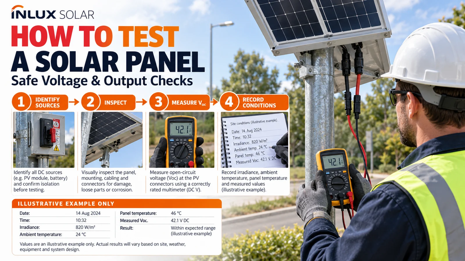
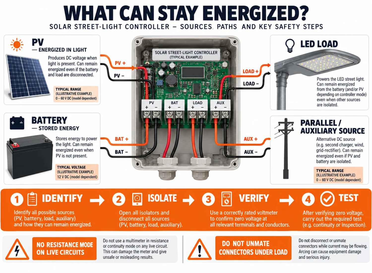
Before you test: know what can stay energized
The U.S. Occupational Safety and Health Administration warns that solar workers can face shock, burn, arc-flash and fall hazards when connecting panels to electrical circuits (OSHA solar electrical hazards). Covering a module can reduce light, but a cover, cloud or switched-off load should not be treated as proof of zero voltage.
Before touching conductors or opening an enclosure:
- identify every source—PV, battery, controller load, utility, generator or another parallel module;
- obtain the wiring diagram, product manual and approved isolation sequence;
- keep the work dry and stable, with no unsafe work at height;
- use a meter, leads, probes, fuses and accessories rated above the maximum possible DC voltage and current;
- inspect the instrument and leads before use;
- verify the meter on a known source before and after the measurement where the work procedure requires it;
- do not disconnect a connector under load unless the connector and procedure explicitly permit it;
- never use resistance or continuity mode on an energized circuit;
- save controller settings and logs before resetting or changing anything;
- follow the employer’s electrical safe-work and lockout/tagout procedure.
OSHA’s solar lockout/tagout guidance notes that PV and connected circuits can expose workers to unexpected electrical energy and that energy sources must be identified and isolated. This article is a measurement framework, not authorization to work on energized equipment.
Read the solar panel label before reading the meter
A measurement is useful only when there is a reference. Photograph the module label and retrieve the model-level datasheet. Record:
| Label or datasheet field | Meaning | Why it matters during testing |
|---|---|---|
| Pmax or Wp | Maximum rated power at stated test conditions | Not the output to expect in every field condition |
| Voc | Open-circuit voltage | Reference for a disconnected voltage check and maximum-voltage design |
| Isc | Short-circuit current | A current reference; direct Isc testing needs an approved safe procedure |
| Vmp | Voltage at maximum power | Useful when the module is operating under a compatible load/controller |
| Imp | Current at maximum power | Combined with Vmp to describe rated operating power |
| Temperature coefficients | Change in electrical behavior with cell temperature | Needed when comparing field values with reference conditions |
| Maximum system voltage | Module insulation/system boundary | Not the same as the expected voltage of one module |
| Fuse or overcurrent field | Manufacturer’s protection limit | Does not grant permission to short the module through a meter |
| Connector/polarity | Approved connection and positive/negative identification | Prevents reversed or incompatible connections |
The nominal name can mislead. A module sold for a “12 V” battery system normally needs an operating voltage above battery voltage under suitable conditions, and its open-circuit voltage will be higher again. Use the actual label, not the marketing category.
Why field watts rarely equal nameplate watts
PV nameplate values are commonly stated at Standard Test Conditions: 1,000 W/m² irradiance, 25°C cell temperature and an AM1.5 reference spectrum. A field panel may receive less than 1,000 W/m² while its cells run well above 25°C, so an instant reading below Pmax is not automatically a defect. Confirm the conditions printed on the exact datasheet because other ratings can also appear.
Temperature coefficients help normalize the comparison. As an illustrative calculation only, if a module datasheet lists a Voc coefficient of −0.28%/°C and the measured cell temperature is 45°C rather than 25°C, the 20°C difference corresponds to an estimated Voc change of about −5.6% before considering instrument and condition uncertainty. Use the manufacturer’s actual coefficient, sign convention and correction method; do not reuse these fictional numbers as an acceptance threshold.
Tools for solar panel testing
Choose the instrument for the question.
| Question | Suitable evidence | Limitation |
|---|---|---|
| Is the module visibly damaged? | Inspection, photographs, serial record | Cannot prove electrical performance |
| Is DC voltage present? | Properly rated digital multimeter | Voc alone cannot prove usable power |
| Is current flowing through the system? | Rated DC clamp meter or controller telemetry | Accuracy and conductor access matter |
| What are Vmp, Imp and power under load? | Compatible load/controller plus voltage and current records | Conditions must be recorded |
| Does the full I-V curve look normal? | PV I-V curve tracer with irradiance and temperature inputs | Specialist tool and trained interpretation |
| Is there an intermittent connector loss? | Voltage-drop/thermal/inspection evidence under an approved procedure | Do not disturb energized connectors casually |
Fluke’s current solar-panel testing guide describes technician use of a digital multimeter for voltage and an I-V curve tracer with irradiance and temperature sensing for fuller module analysis. Brand-specific tool recommendations are not universal project requirements; the transferable rule is to match the instrument, range and procedure to the circuit and measurement purpose.
How to test a solar panel step by step
1. Define the test question
Do not begin by moving the probes around until a number appears. State what you are trying to establish:
- physical damage or contamination;
- correct polarity and connection;
- presence of open-circuit voltage;
- operating voltage/current under the installed load;
- comparison between otherwise equivalent modules;
- controller input versus module output;
- post-installation acceptance baseline;
- suspected intermittent or temperature-related fault.
One test cannot answer all eight questions.
2. Record sunlight, shade and module temperature
Panel current changes strongly with irradiance; voltage also changes with operating condition and cell temperature. Record the date, local time, sky condition, panel orientation, visible shade and module temperature. For a formal performance comparison, use suitable irradiance and temperature instruments and the module manufacturer’s correction method.
Do not compare a cool clear-morning measurement with a hot hazy-afternoon datasheet value and call the difference a defect. The direct-sunlight guide explains why a panel that looks bright can still receive a weak or interrupted charging window. For design context, the worst-month solar resource guide separates a momentary electrical test from the daily energy available to recharge a battery.
3. Perform a visual and mechanical inspection
With the equipment in the approved safe state, inspect both faces and the entire cable path:
- cracked or chipped glass;
- delamination, bubbles, discoloration or hot-spot evidence;
- bent frame or loose mounting hardware;
- damaged backsheet or junction box;
- loose cable glands or unsupported leads;
- incompatible, open, wet, overheated or corroded connectors;
- reversed polarity labels or undocumented adapters;
- dirt, bird deposits, leaves, snow or a new shadow;
- abrasion where cable touches the pole or bracket;
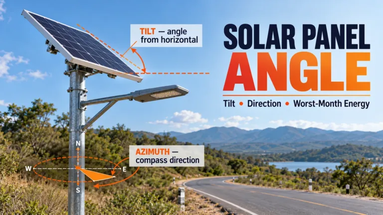
- panel angle changed from the approved drawing.
Photograph the defect beside the pole or asset ID. Cleaning a dirty module before recording its original state removes useful evidence.
4. Check open-circuit voltage only under an approved procedure
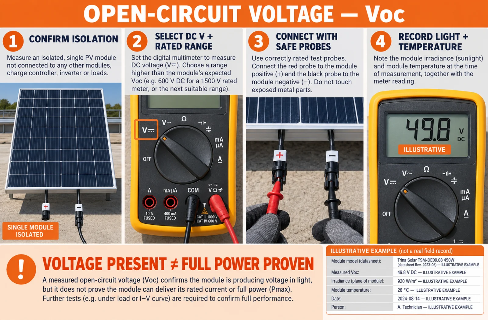
Open-circuit voltage, or Voc, is measured across the positive and negative module outputs when no load is connected. Because the module is illuminated, the conductors are live during the reading.
For a permitted single-module test, a qualified person typically confirms the module is isolated from the controller, battery and other sources, sets a suitable meter to DC voltage, verifies polarity and connects rated probes without exposing fingers to conductive parts. The result is recorded with irradiance/sky and temperature.
Interpret Voc cautiously:
- near-zero can indicate no light, an open internal path, wrong contact, a damaged lead or instrument/setup error;
- reversed sign usually indicates reversed probe polarity or mislabeled connections;
- a plausible Voc proves voltage is present but does not prove the module can deliver current or power;
- a value different from the label may be normal because label values use stated test conditions;
- cold conditions can raise Voc, which also matters for controller maximum-input design.
Do not connect the module back into a live controller circuit by pulling or mating connectors under load.
5. Do not improvise a short-circuit current test
Isc is a datasheet parameter, but placing a meter directly across an illuminated module in current mode deliberately creates a short-circuit path. A wrong socket, range, fuse, lead, connector or circuit assumption can damage the meter or expose the worker to arcing and burns. Parallel modules, strings and connected storage make the risk much greater.
Only perform an Isc test when the module manufacturer, test instrument and site procedure allow it, and when a competent person has verified the maximum possible voltage/current, instrument DC rating, fused input, connection sequence and PPE. Do not apply a loose-module internet demonstration to an installed array or pole-mounted system.
For routine field diagnosis, safer and more useful options may include:
- rated DC clamp-current measurement on an accessible conductor under known operation;
- controller PV input current and voltage, if the telemetry is verified;
- a compatible electronic load;
- a PV multifunction tester;
- an I-V curve tracer with irradiance and temperature records.
6. Measure operating voltage and current under a known load
Power requires both voltage and current:
Electrical power (W) = operating voltage (V) × operating current (A)
Suppose a fictional test records 17.8 V and 4.6 A at the controller input under documented sunlight:
17.8 V × 4.6 A ≈ 81.9 W
That number is not an Inlux product result and cannot be compared directly with a nameplate Pmax without irradiance, cell temperature, wiring loss, controller operating point and instrument uncertainty. It is still useful as a repeatable field record or for comparing equivalent units tested together.
Where possible, measure at both ends of a cable segment under the same operating state. A substantial difference can indicate connector, cable, fuse or termination loss rather than a weak module.
Record measurement uncertainty before judging the panel
Two readings that look different may still be indistinguishable once instrument accuracy and changing sunlight are considered. Before declaring a pass, fail or percentage loss, record the meter range and stated DC accuracy, clamp-meter resolution where used, calibration status, irradiance change during the test, module-temperature change and the time gap between comparison readings.
For example, a technician should not report a precise 4% module loss when the comparison used different cloud conditions, an unverified controller operating point and instruments whose combined uncertainty could be of similar size. Repeat the measurement under stable conditions, test matched modules in quick succession and retain the raw readings. If a contract requires a formal acceptance tolerance, use the project specification and an approved correction method rather than inventing a field percentage.
For a repeatability check, capture at least 3 readings at the same test point and note the elapsed time—such as 0, 30 and 60 seconds—only while conditions and the approved operating state remain stable. Keep all 3 values; an average without the minimum, maximum and changing-sunlight note can hide an intermittent connection or passing cloud.
Also label the electrical test point. “Panel voltage” might mean module leads, the controller PV terminals or controller telemetry; cable and connector losses sit between those locations. A defensible record says where the probes or sensor were placed.
7. Compare like with like
When several identical street lights share similar orientation and sunlight, compare them in the same time window. Record panel model, cleanliness, shade, controller state, battery state and load program. An outlier among matched units can be more diagnostic than comparison with a laboratory rating alone.
Do not compare:
- different module wattages or cell counts;
- one clean and one shaded panel;
- different controller tracking states;
- one battery near full charge and another deeply discharged;
- readings taken hours apart under changing clouds;
- a module-level probe with controller app data from another electrical point.
8. Escalate to an I-V curve or laboratory test when needed
Voc and one current value are snapshots. An I-V curve shows module behavior across a range of operating points and can reveal patterns that a single reading misses. Formal comparison still requires irradiance, temperature, model data and trained interpretation.
IEC 62446-1:2016 covers documentation, commissioning tests and inspection for grid-connected PV systems (IEC publication record). An off-grid solar street light is not automatically within every clause of that standard, but its documentation principle is useful: tests, instruments, results and handover evidence should be defined, not improvised after a fault.
What the readings can and cannot prove
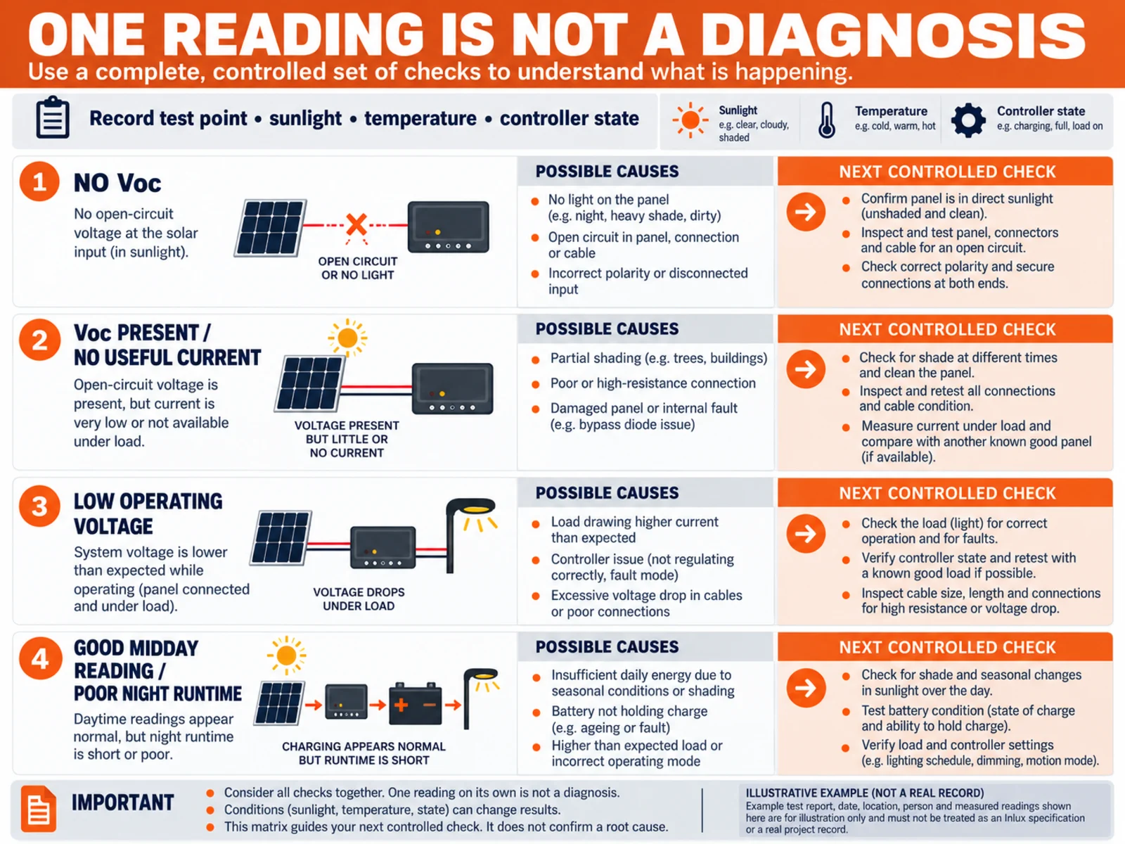
| Observation | Possible explanations | Next controlled check |
|---|---|---|
| No Voc | No light, open circuit, broken cable/junction, poor probe contact, wrong setup | Verify instrument and isolation, inspect cable/junction, retest under known light |
| Voc present, no useful current | Weak irradiance, severe damage, poor connection, wrong controller state, instrument/setup issue | Record irradiance; inspect; test operating current with suitable equipment |
| Normal Voc, low operating voltage | Heavy load, controller behavior, cable drop, battery state, connector resistance | Record both ends of cable and controller state under the same load |
| Current lower than a matched unit | Shade, dirt, orientation, mismatch, degradation, bypass-diode/cell issue | Clean/inspect; compare conditions; use I-V/thermal evidence if required |
| Good midday snapshot, poor night runtime | Daily shade, seasonal resource, battery capacity, schedule, controller or load problem | Review charging history and complete energy balance |
| Intermittent reading | Loose connector, cable movement, moisture, thermal behavior, measurement contact | Isolate and inspect; do not wiggle energized connectors |
A normal Voc does not certify rated power. A normal module does not certify a healthy battery. A high noon current does not prove enough daily energy. The How Solar Lights Work guide shows why panel, controller, battery and load evidence must remain separate.
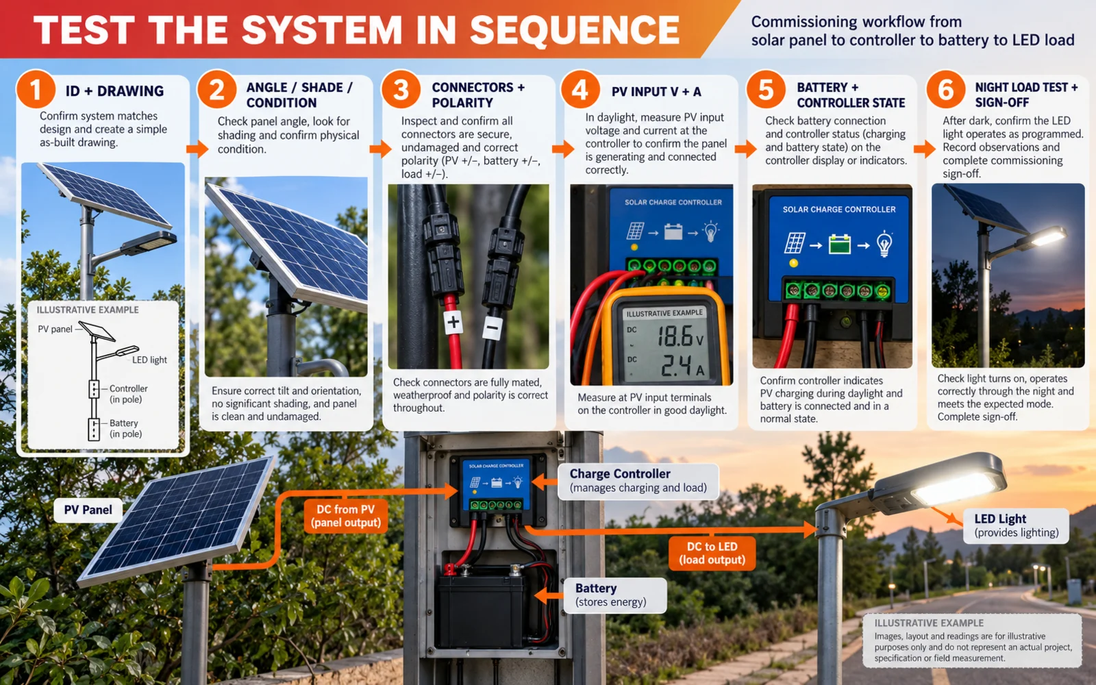
Solar street-light commissioning test sequence
Testing a street-light panel is one part of a system acceptance check. Use a consistent order so a battery or controller fault is not blamed on the PV module.
- Confirm pole ID, coordinates, panel model, serial/batch and approved drawing.
- Verify panel tilt, direction, cleanliness and charging-window shade.
- Inspect bracket, cable support, glands, connectors and polarity.
- Record weather, time, module temperature and irradiance/sky condition.
- Record panel Voc only where the approved isolation/test procedure requires it.
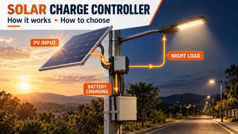
- Record controller PV input voltage/current and charging state under operation.
- Record battery voltage, BMS/controller state and any alarms without treating voltage alone as capacity.
- Confirm the programmed dusk, dimming and load schedule.
- Perform the required night test and record LED load behavior.
- Save instrument model/serial, calibration status, technician, photos and pass/fail criteria.
For the next stage, use the solar street-light installation guide for foundation-to-handover work and the battery sizing guide to check stored-energy requirements. If you are preparing a tender, the quality and testing evidence page explains the supporting records to request alongside the panel test results.
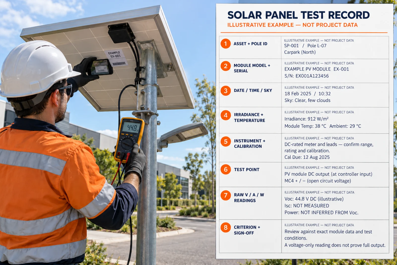
Copy-paste solar panel test record
| Field | Required entry |
|---|---|
| Asset | Project, pole ID, coordinates, drawing revision |
| Module | Manufacturer, model, serial/batch, Pmax, Voc, Isc, Vmp, Imp |
| Condiciones de prueba | Date/time, sky, irradiance where measured, module temperature, shade, tilt/direction |
| Safety control | Isolation procedure, identified energy sources, qualified person and test boundary |
| Instrument | Type, model, serial, calibration status, DC voltage/current rating, lead/probe set |
| Visual result | Glass, frame, backsheet, junction, connector, cable, gland, bracket and photos |
| Electrical result | Voc; operating voltage/current/power; controller state; test point |
| Comparison | Datasheet condition/correction or matched-unit reference |
| Aceptación | Criterion, pass/fail, anomaly and required corrective action |
| Sign-off | Technician, reviewer, date and attachment IDs |
Inlux Solar has delivered more than 300,000 lighting units across 60+ countries. A global project base does not make one meter value universal; it makes model, site and test-condition traceability more important. If a project needs technical review, send the panel label, controller and battery models, pole layout, lighting schedule, fault pattern, readings and photographs through the project enquiry page.
How this page differs from solar-light troubleshooting
This page answers how to test a PV module and record defensible electrical evidence. The solar lights not working guide starts with the symptom and follows the whole chain through sensor, controller, battery, wiring and LED load. Use the test method here only when the broader diagnosis points to the panel or its circuit.
Preguntas frecuentes
How do I test if a solar panel is working?
Start with the module label and a safe visual inspection. Under an approved isolation procedure, a qualified person can check open-circuit DC voltage with a correctly rated meter, then record operating voltage and current under a known load or through verified controller telemetry. Compare the result with the exact datasheet and measured conditions; voltage alone does not prove full power.
Can I test a solar panel with a multimeter?
Yes, for measurements within the meter, lead and procedure ratings. A multimeter can check DC voltage, and some instruments can measure current, but a direct short-circuit current test is not a casual step. Confirm the maximum possible values, fused input, correct socket/range and isolation method. Use a qualified technician for installed or higher-energy systems.
What voltage should a solar panel show?
There is no universal pass voltage. Compare the measured open-circuit voltage or operating voltage with the exact module’s Voc or Vmp, then account for sunlight, module temperature and measurement uncertainty. A “12 V panel” label is a system category, not the expected meter reading in every condition.
How can I test a solar panel without a multimeter?
You can inspect damage, shade, dirt, connectors and controller status; compare charging telemetry or nighttime performance with an equivalent unit; and review logged energy. These checks can identify a likely problem but do not replace electrical measurements. Do not connect a random lamp or battery as an improvised test load.
Why does a panel show voltage but not charge the battery?
Voc can look plausible while the module cannot supply useful current, the cable has a high-resistance fault, the controller blocks charging, the battery/BMS refuses charge or the battery is already at a charge limit. Measure the system in sequence and record the controller state instead of replacing the panel from one voltage reading.
Can I test a solar street-light panel while it is on the pole?
Only under an approved access and electrical safe-work plan. Working at height adds fall, lifting and dropped-object risks, while the illuminated panel and battery may keep circuits energized. Use accessible controller telemetry and ground-level inspection first; isolate and lower equipment where the product and site procedure allow it.
The result that matters
The useful outcome is not “the meter showed a number.” It is a traceable conclusion: which module was tested, at which electrical point, under what sunlight and temperature, with which instrument and safety controls, against which model-level criterion—and what action follows.