






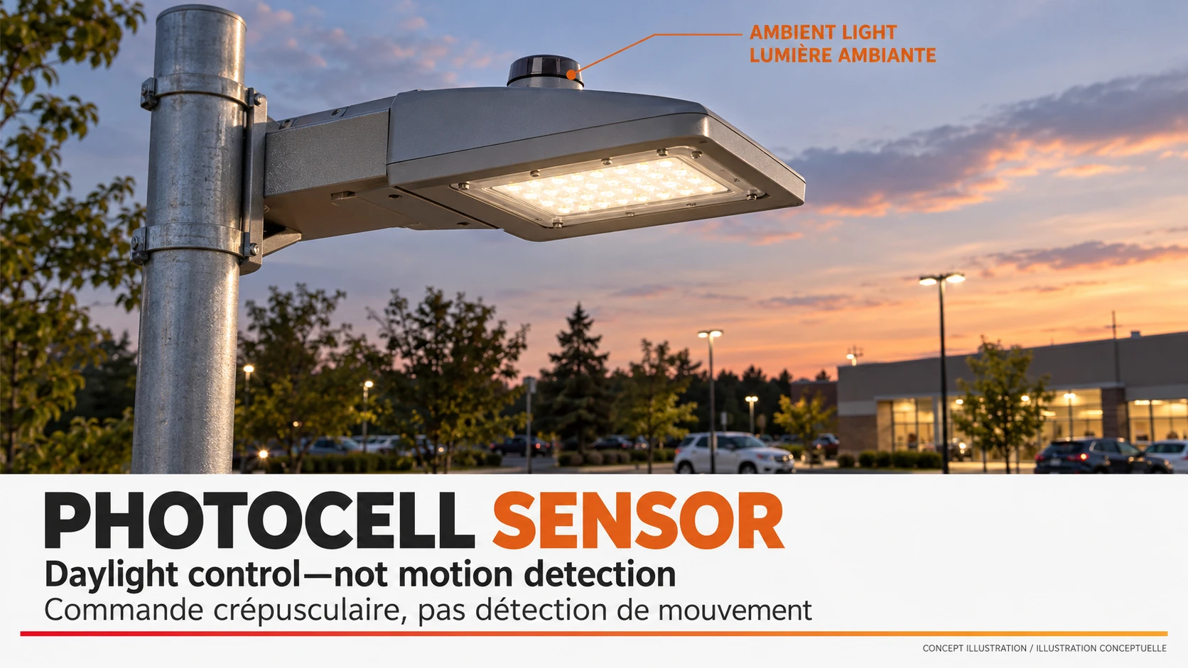
A photocell sensor for outdoor lighting detects ambient light and gives a control system the information needed to switch lights as daylight changes. It does not detect people, measure useful light across a road, or generate electricity like a solar panel. Before buying one, identify the complete photocontrol—not just the small light-sensitive element inside it—and match it to the luminaire and supply.
The distinction matters when an existing light stays on all day or a contractor is pricing replacement controls for a group of poles. A sensor that looks identical may have a different voltage range, load rating or response. Buying by the housing colour or a large wattage printed on a retailer’s listing is a poor substitute for the original part reference and the applicable datasheet.
Start by identifying what “photocell” means in the offer
In lighting procurement, “photocell sensor,” “photoeye” and “photocontrol” are often used loosely. The supplied item might be a complete switching control, a low-voltage sensing input or a bare electronic component. These are not interchangeable. A photoelectric detector used to detect an object or a vehicle is another device again; the shared word “photo” does not establish the same function.
| Device described in the offer | Job performed | Buyer’s first identification task |
|---|---|---|
| Complete lighting photocontrol | Senses daylight and switches a rated lighting load | Find supply and load ratings for the exact reference |
| Light sensor feeding a controller | Supplies an input to another control device | Identify the required signal and the receiving equipment |
| Bare light-dependent component | Changes an electrical property with light | Do not substitute it for a complete outdoor switching unit |
| Solar controller with day/night detection | Uses its supported detection method to run a lighting programme | Check the complete solar system’s control architecture |
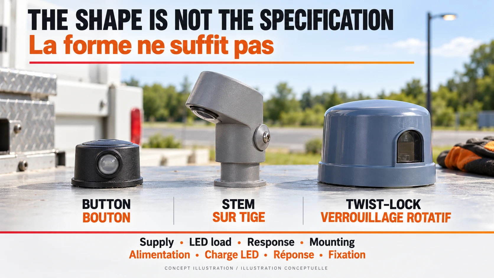
Button, stem-mounted and twist-lock units describe physical arrangements, not a universal electrical specification. This guide addresses component identification and replacement decisions. For the broader choice between daylight sensing, timers and other operating strategies, use our dusk-to-dawn outdoor lighting guide instead of treating every night-time control as the same part.
Read the LED load line, not the largest wattage
A photocell sensor must be compatible with both its own supply and the load it switches. An AC photocontrol is not automatically suitable for a battery-powered DC light. A low-voltage input sensor is not automatically a mains switching device. Ask the luminaire supplier to confirm the proposed control and driver combination, including how many luminaires the control will operate.
LED drivers can draw a brief starting current that is very different from their normal operating current. A label intended for an incandescent or magnetic-ballast load does not, by itself, approve the same numerical load of LED equipment. For a group of lights, request the control manufacturer’s permitted LED or electronic load and any stated driver-count or inrush restrictions. Do not calculate a safe quantity from watts alone.
A concrete illustration is the published specification for Intermatic ELC4036, which lists supply, electronic-ballast load, lamp compatibility and time delay separately. The K4223C page describes a different thermal control. The comparison below shows why the exact reference matters; these are third-party examples, not parts specified for an Inlux product.
| Published example—not an Inlux configuration | ELC4036 | K4223C |
|---|---|---|
| Listed supply | 120–277 VAC | 208–277 VAC |
| Listed control type | Electronic | Thermal |
| Application list on the cited page | Includes LED | Lists fluorescent, HID and incandescent; obtain separate LED approval |
| Published response delay | ON 15–30 s; OFF 2–5 s | 30–90 s |
| Selection consequence | Use the relevant load-specific rating | Do not infer equivalence from appearance or a larger lamp-load number |
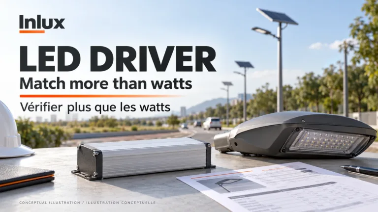
Record the supply, driver reference, number of luminaires and control reference together. If any one changes, the approval needs reviewing. For the driver side of that comparison, our outdoor LED driver guide explains the matching boundary without turning a purchasing check into a live electrical test.
Switching delay and sensor position are part of the specification
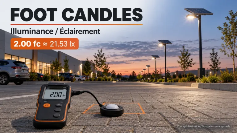
The light level seen by a photocell sensor is local to the sensor. It is not a measurement of illuminance across the carriageway or parking surface. An overhang, dirty sensing window, illuminated sign or reflected light can therefore change switching behaviour even when the lighting requirement on the ground has not changed. Follow the exact manufacturer’s orientation and installation instructions; a compass-direction rule copied from another product is not enough.
Switch-on and switch-off thresholds need not be identical, and a time delay can prevent a brief disturbance from immediately changing the output. That also means an instant response is not a universal pass criterion. Specify the applicable thresholds and delays from the approved product, then have qualified commissioning personnel verify the installed response with the normal supply and control programme in place.
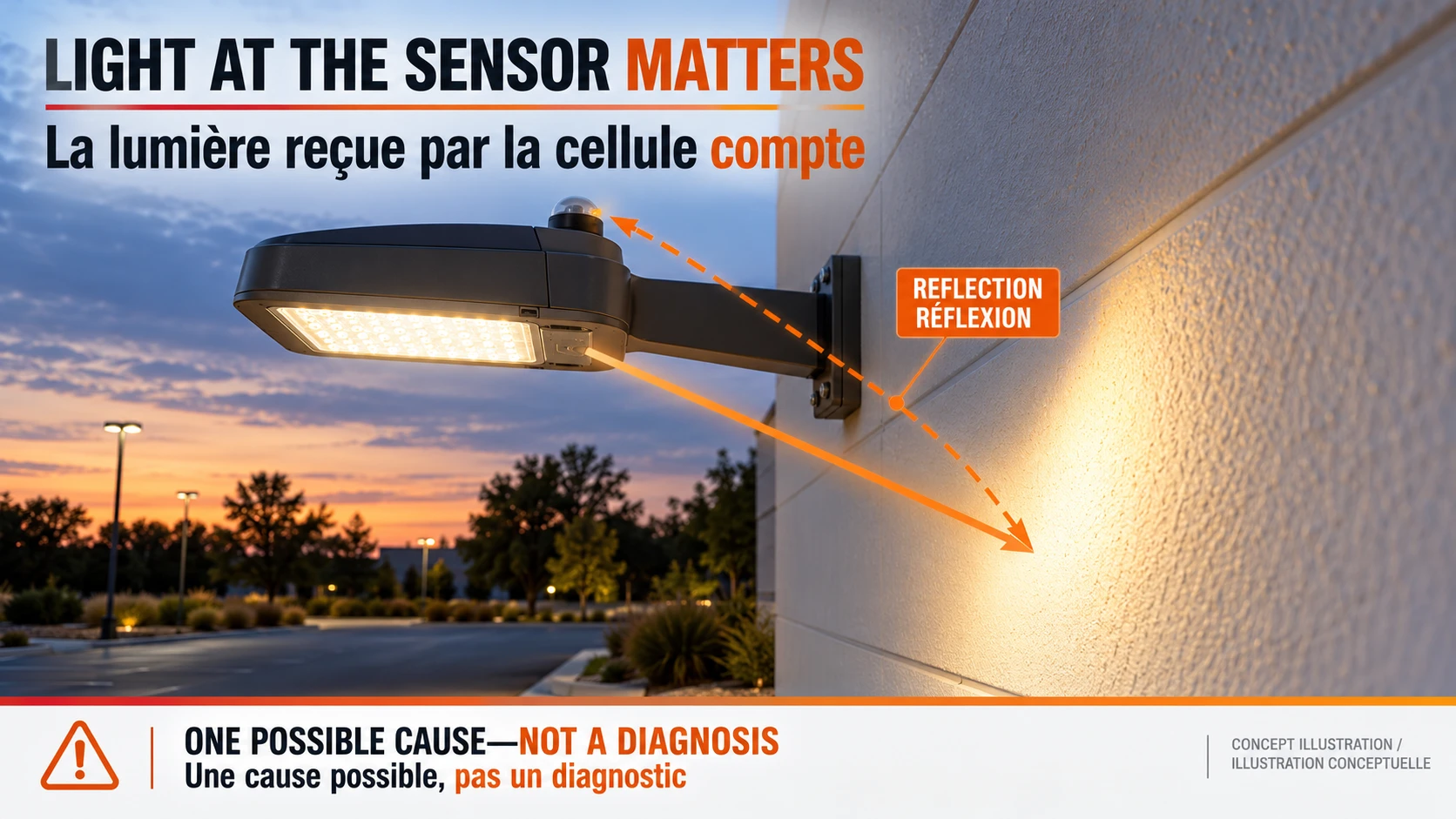
A light that illuminates its own sensor directly or by reflection may create an unwanted feedback loop. But repeated switching is not proof of that cause: a driver fault, an unstable supply or another control can produce a similar complaint. Photographs of the sensor’s view, the surrounding light sources and the timing pattern are more useful to a service team than an unsupported instruction to replace every sensor.
A fault report should separate observations from diagnosis
Start with observations that can be made safely from ground level and with the available asset records. Do not remove a control, expose conductors, bridge contacts or bypass a protective function to prove a point. Opening a luminaire, electrical measurements and replacement belong to qualified personnel using the manufacturer’s procedure and the site’s isolation and access arrangements.
| Reported symptom | Evidence worth collecting safely | What the symptom does not prove |
|---|---|---|
| Light remains on during daylight | Asset reference, control mode, timing, visible sensor obstruction and recent changes | The photocell is necessarily defective |
| Light remains off after dark | Whether other lights are affected, override status and available fault logs | The daylight sensor is the failed component |
| Light repeatedly switches | Time pattern, weather, nearby light sources and whether the whole group is affected | Optical feedback is the only explanation |
| Solar light dims or stops before morning | Controller status, operating schedule and available battery/charging history | A separate photocell needs replacement |
If several fittings change together, report the group pattern before ordering individual components. If one fitting behaves differently from comparable neighbouring fittings, include its exact references and any maintenance history. Both observations help narrow the investigation, but neither authorises an unqualified person to work on the circuit. Keep the distinction between a suspected cause and a confirmed diagnosis in the maintenance record.
Solar street lights may detect night without a separate photocell
Some solar controllers infer day and night from the PV input rather than a separate mains photocell sensor. The Victron SmartSolar streetlight settings, for example, describe PV-voltage detection and delays. This establishes one documented architecture, not the settings or hardware used by every Inlux model. Do not copy its voltage thresholds into another product.
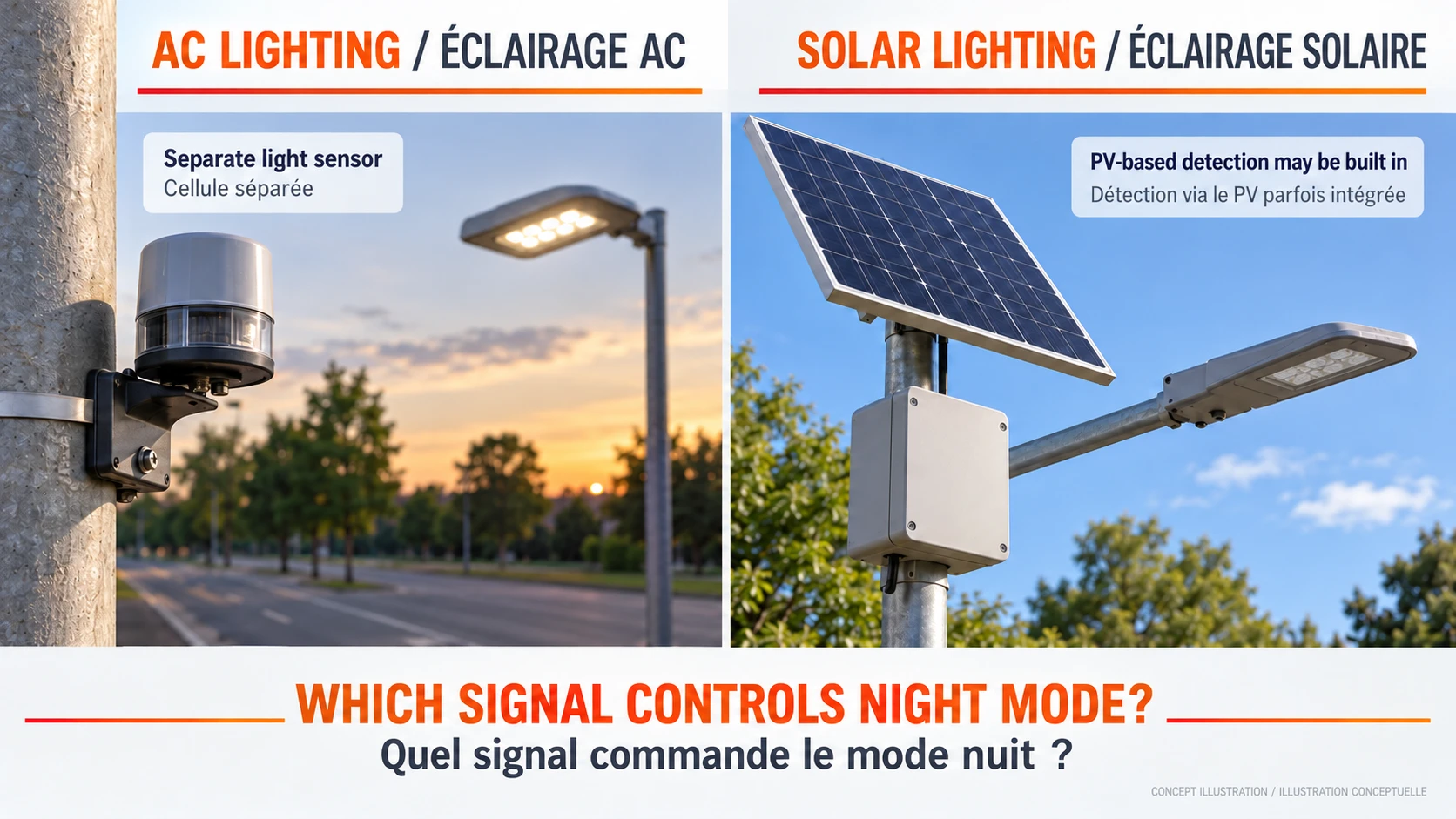
Before specifying a replacement for a solar light, identify what signal actually enables night mode, which controller owns the schedule and which protections can inhibit the load. Our solar charge controller guide explains that system boundary. For a project enquiry involving the Inlux All-in-One range, request confirmation of the quoted model’s control arrangement rather than adding an unrelated AC sensor to the parts list.
What to send with a control or replacement enquiry
Send a readable original control reference, luminaire and driver references, supply details, quantity, mounting photographs taken safely, the observed symptom and the required operating behaviour. Ask whether the proposed part is an exact replacement or an approved alternative. The answer should state the load-specific approval and any required commissioning, not just “same size” or “works with LED.”
Compare the component price separately from access equipment, qualified labour, commissioning and delivery. A low-priced photocell sensor can be an expensive replacement if the wrong part requires another visit. Inlux Solar’s standard warranty is 5 years; for an Inlux system, confirm the applicable service route before modifying it. That company policy does not make an unrelated replacement control automatically approved or covered.
الأسئلة المتداولة
Does a photocell sensor dim an LED light?
A basic photocontrol switches its approved load on or off. Dimming requires a compatible control function and driver; daylight detection alone does not establish that capability. State the required night-time output profile when requesting the luminaire so the supplier can identify the correct control architecture.
Should a new photocell respond immediately?
Not necessarily. The approved device may have different delays for switching on and off. Compare the observed response with its exact instructions rather than applying one delay to every sensor. Repeated short interruptions or an improvised cover test can give a misleading result; let qualified commissioning personnel use the manufacturer’s method.
Can I replace a photocell with one that looks the same?
Appearance is insufficient. Check the exact supply, switching function, load-specific rating, mounting, environmental suitability and required response. Obtain approval for the actual luminaire or group of luminaires. Replacement is an electrical maintenance task, not simply a housing swap.
Does a light staying on all day prove the photocell is bad?
No. Obstruction, an override, a different control mode or an electrical fault can create a similar report. Record the timing and visible conditions safely, then have qualified personnel investigate. Do not bypass the control or expose wiring as a quick diagnostic shortcut.
Does every solar street light need a separate photocell sensor?
No. Some systems already provide day/night detection in the solar controller, and others use a different approved arrangement. Check the exact model’s documentation. A mains-rated photocontrol should not be added to a battery system merely because both products are described as dusk-to-dawn.
How much does replacing a photocell sensor cost?
There is no useful universal installed price. It depends on the approved part, quantity, location, safe access, labour and commissioning scope. Request a quote that separates those items and identifies the replacement reference. A component-only retail price is not a complete maintenance budget for pole-mounted lighting.
Specify the lighting system before ordering the control
For an AC road-lighting project, start with our LED street light range and state the supply, control requirement and maintenance arrangement. For commercial solar parking lot lighting, send the site and night-time operating requirements first. Browse our solar street light product range for complete systems; Inlux enquiries should concern a confirmed lighting configuration, not an assumed universal sensor replacement.