







The voltage drop formula for a simple DC circuit is ΔV = I × Rloop. Rloop must include both outgoing and return conductors; using only the distance from source to load understates the loss. For solar street lighting, the useful question is not just “what percentage is lost?” It is whether the selected controller or light still receives an acceptable voltage under the specified operating conditions.
A quotation can include enough metres of cable and still leave that question unanswered. Pole rises, enclosure positions and the final route may differ from the sketch used for pricing. This guide explains how to read the calculation before accepting a cable allowance or changing a solar-lighting layout. It is a procurement review, not an installation or live-testing procedure.
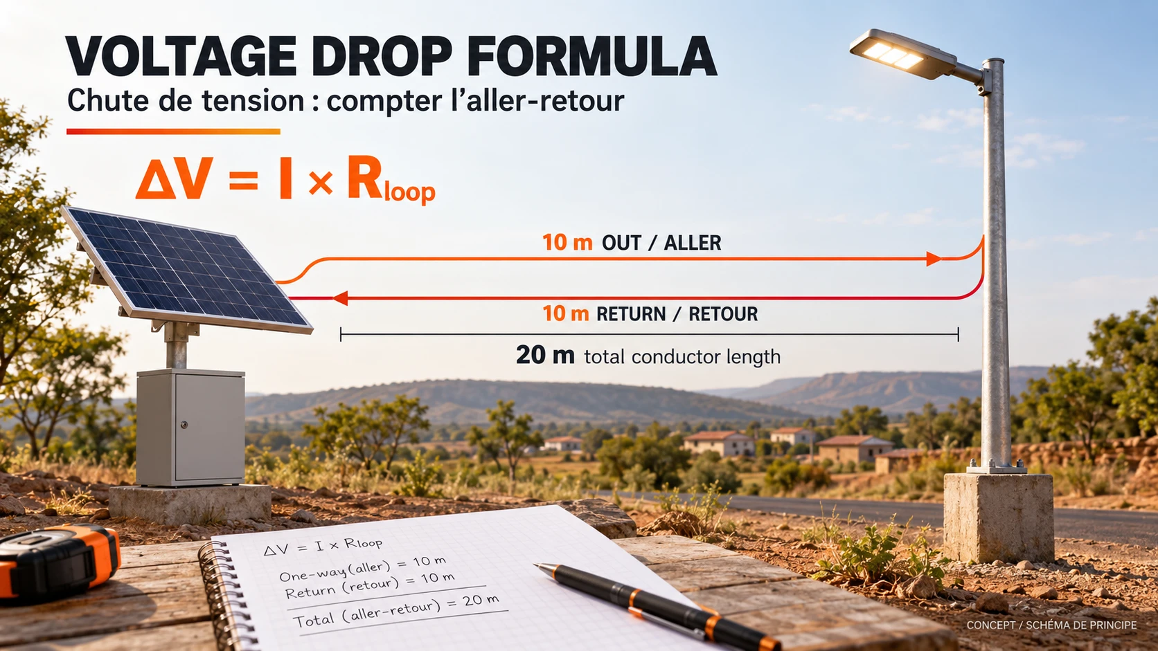
DC voltage drop formula: define the loop first
For a two-conductor DC supply with equal conductor resistance per metre, use Rloop = 2 × L × r, then ΔV = I × 2 × L × r. Here L is the one-way route length and r is resistance per metre of one conductor. If the outgoing and return paths differ, calculate their resistances separately and add them. Do not double a resistance value that already represents the complete loop.
| Symbol | Meaning | Unit or boundary |
|---|---|---|
| ΔV | Voltage lost across the assessed path | V |
| I | Current through that path at the assessed operating point | A; not automatically the LED nameplate current |
| L | One-way installed route | m; include the actual route, not a straight-line site distance |
| r | Resistance of one conductor per unit length | Ω/m; use the stated conductor and temperature basis |
| Rloop | Combined outgoing and return resistance | Ω; identify any additional connection resistance separately |
If a cable data sheet gives Ω/km, divide that value by 1,000 before using lengths in metres. A material-based estimate can instead use R = ρ × length ÷ area, provided resistivity, length and conductor cross-sectional area use consistent units. For a supplier comparison, a documented resistance value for the actual cable is usually more useful than an unexplained generic copper constant.
These relationships follow ordinary circuit theory. Victron’s Wiring Unlimited theory chapter explains conductor resistance, connection losses and DC voltage drop. Its equipment examples are not specifications for Inlux products. The equations here describe a simplified steady DC path; AC circuits, electronic conversion and changing loads need the appropriate design method.
A worked example you can check without guessing a cable size
Assume a source is supplying 24.00 V at a particular operating point. The load current is 5 A, the outgoing route is 10 m and the return route is also 10 m. For this example only, assume each conductor has a resistance of 0.005 Ω/m at the assessed conditions. No cable size, temperature rating or Inlux configuration is implied by these invented inputs.
| DC calculation | Result | What it establishes |
|---|---|---|
| Rloop = (10 + 10) × 0.005 | 0.10 Ω | Combined conductor resistance |
| ΔV = 5 × 0.10 | 0.50 V | Conductor voltage loss at 5 A |
| Vload = 24.00 − 0.50 | 23.50 V | Load-side voltage before other losses |
| Drop % = 100 × 0.50 ÷ 24.00 | 2.08% (rounded) | Loss relative to the stated source voltage |
| P_loss = 5² × 0.10 | 2.50 W | Conductor heating loss at this operating point |
The easy mistake is to enter 10 m as the total conductor length. That produces 0.25 V instead of 0.50 V: half the calculated loss has disappeared on paper, not in the installation. A second mistake is to use a loop-resistance figure and multiply it by two again. Ask the supplier to label the length convention on the calculation rather than relying on a column headed “distance.”
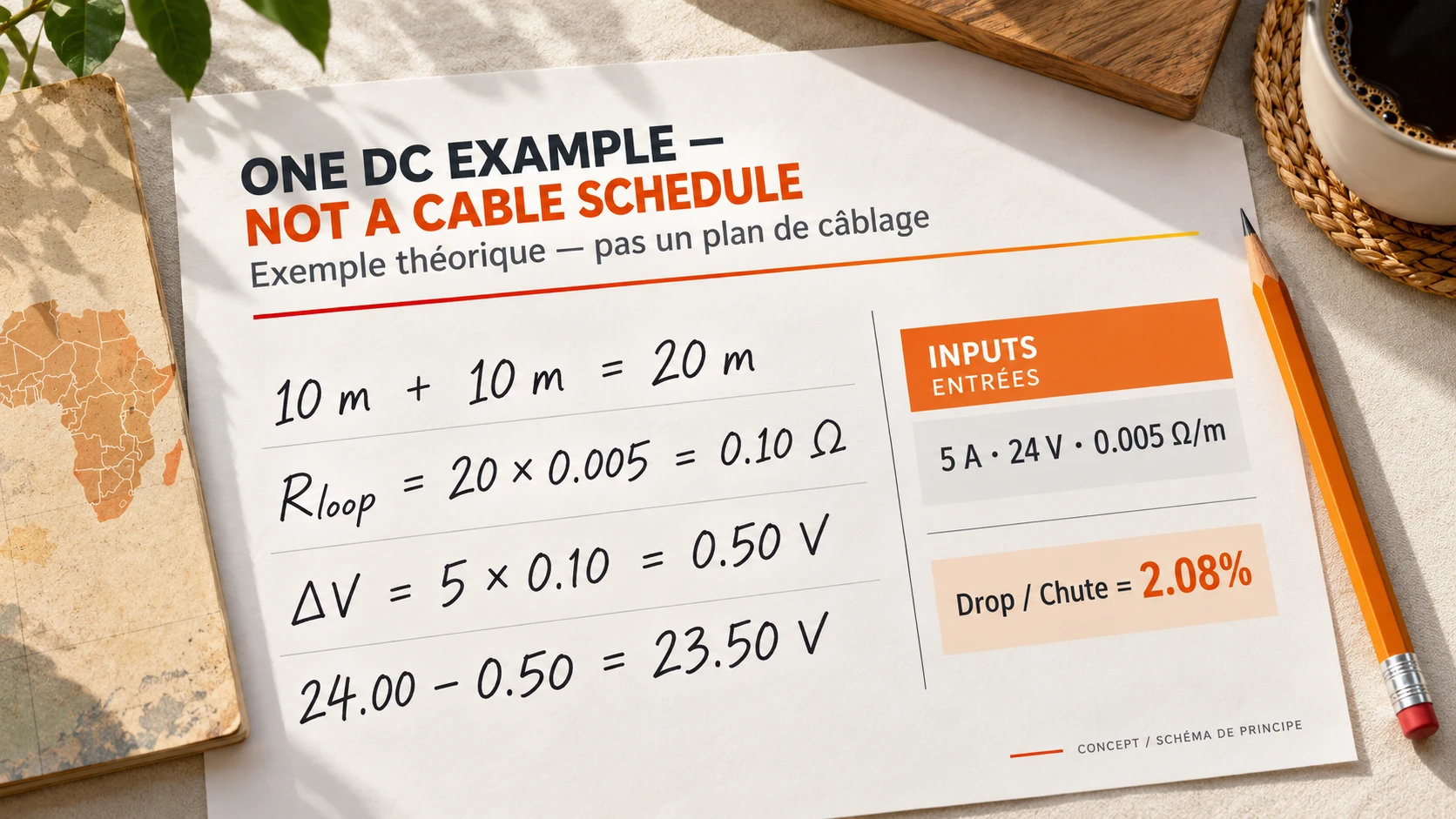
This example holds current and resistance fixed to make the arithmetic visible. It does not establish a permissible cable, fuse or operating voltage. Actual cable resistance, installation conditions, terminations and equipment behaviour remain part of the project designer’s assessment. A neat calculation with missing assumptions is still an incomplete quotation.
A percentage is not the receiving device’s input window
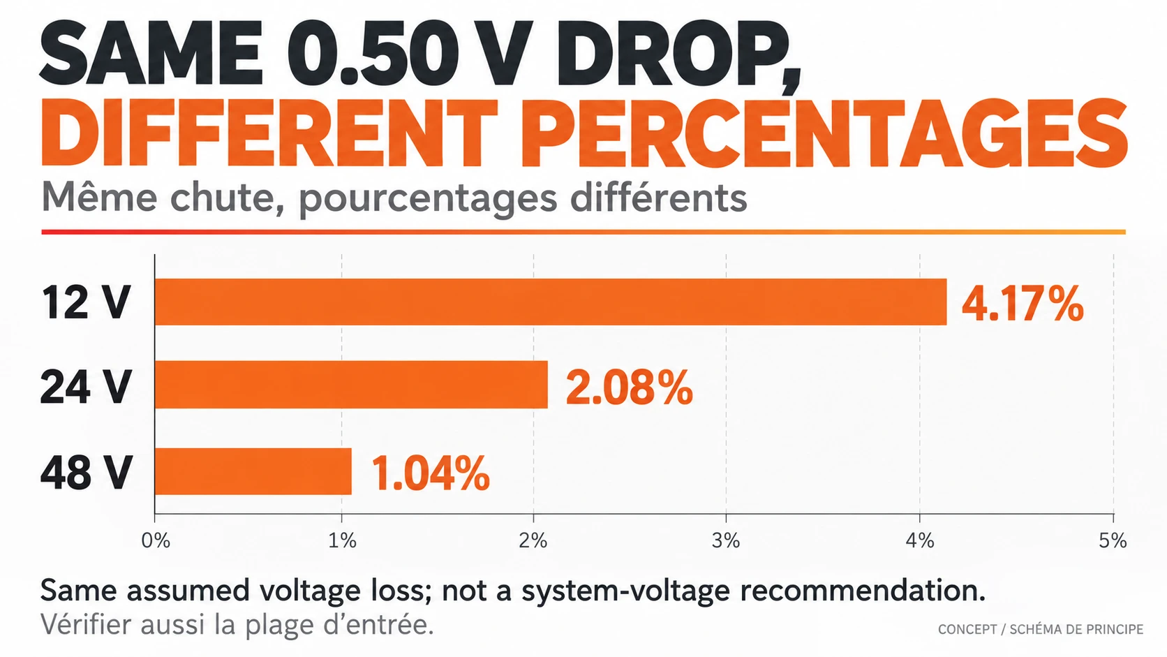
Voltage drop percentage is 100 × ΔV ÷ the stated reference voltage. The same assumed 0.50 V loss is 4.17% of 12 V, 2.08% of 24 V and 1.04% of 48 V. Those figures compare denominators only. They are not a claim that three real systems have equal losses, or advice to change a product’s system voltage.
The next check is absolute voltage. Ask for the source-voltage range and the receiving device’s permitted input range under the relevant conditions. A result below a preferred percentage can still leave too little voltage at the equipment near the lower end of the source range. Conversely, a percentage target alone says nothing about protection, cable heating or the equipment’s upper voltage limit.
Choose the circuit segment before choosing the current
A solar-lighting system has more than one electrical operating point. The PV-to-controller path is not the same circuit segment as the battery-to-controller path or the controller-to-light path. A conversion stage can change voltage and current. The LED wattage printed in a quotation therefore does not, by itself, tell you the current in every cable.
Use the specified design current for the segment being reviewed, including the relevant maximum operating condition. For a regulated load, current can change as input voltage changes; a fixed-current example should not be stretched into an equipment guarantee. For the PV side, the controller’s operating requirements and module electrical data also matter. Keep those limits in the same configuration review; the solar panel wattage guide explains why panel watts alone do not settle compatibility.
Longer routing, a different conductor material or a different temperature basis changes the resistance assessment. Connection losses also need a stated allowance where relevant. Do not compensate for an unexplained bad connection by simply ordering a larger cable. Connector identity and approved mating combinations are a separate issue covered in our MC4 connector procurement guide.
When a solar street light layout change needs a new calculation
Inlux’s current All-in-Two collection lists FALCON, JAGUAR and BISON, while its Split Type collection separates the main components. These are different layout choices, not a reason to apply one cable allowance to every model. For an All-in-Two solar street light project, agree the panel-to-light arrangement. For a Split Type solar street light project, the positions of the separate equipment make the route especially important.
| Proposed change | Useful supplier response | Not enough on its own |
|---|---|---|
| Move the PV module or battery enclosure | Revised route, circuit segment, current and receiving voltage assessment | Extra metres at the old unit price |
| Substitute a cable | Cable reference, resistance basis, installation suitability and terminal compatibility | Same outer diameter or advertised current |
| Change the load or lighting programme | Updated electrical operating conditions and energy assessment | Keeping the old cable calculation unchanged |
| Extend a factory-integrated assembly | Manufacturer-approved configuration and designer review | Assuming a short original harness can simply be lengthened |
An integrated product is not an invitation to modify its internal harness. Review the factory arrangement in the All-in-One solar street light collection rather than treating it as a set of interchangeable loose components. On a parking project, confirm whether each pole is autonomous or the proposal uses another defined architecture; do not infer shared cabling from a row of lights on a site plan.

What to send with a cable-related RFQ
Send the proposed equipment arrangement, actual one-way route for each external circuit, intended lighting programme and any site restrictions. Ask the supplier to identify the calculation basis and the person responsible for final electrical design. If the route is not settled, keep the cable allowance provisional and record what must be confirmed before ordering. That is more useful than agreeing an attractive per-metre price on an undefined route.
For complete-system selection, compare the Inlux solar street light range. For a commercial site, review our solar parking lot lighting options. To discuss a defined layout, send the project route and requirements to Inlux. The quotation should identify the configuration being assessed, not promise that a generic voltage-drop percentage approves the whole installation.
الأسئلة المتداولة
What is the 3% voltage drop rule?
A 3% figure is often used as a design reference, but it is not a universal approval rule for every solar-lighting DC path. The applicable project requirements, local rules and equipment limits must be identified. Ask what the percentage is measured against and whether the receiving device remains within its permitted input range.
What is the voltage drop per 100 ft, or on 12 AWG wire?
Neither length nor gauge gives a single answer without current, conductor properties and operating conditions. Also clarify whether 100 ft means one-way or total conductor length. The Southwire voltage drop calculator uses AWG/kcmil inputs and distinguishes calculation conditions; do not silently mix its units with a metric cable quotation.
How much voltage drop is there over 300 feet?
There is no fixed loss for 300 feet. For the same current and conductor conditions, a longer path has greater resistance, but the acceptable route depends on the equipment and full design. For a remote lighting layout, ask the designer to compare the proposed supply architecture rather than extending a short-run cable assumption.
Can I use LED watts divided by battery voltage as cable current?
Only if those values describe the same electrical operating point and the relevant losses are accounted for. Controller conversion, dimming and changing source voltage can make that shortcut misleading. Request the design current for the particular cable segment instead of applying one nominal calculation to the entire system.
Does a larger cable automatically solve a low-voltage problem?
No. The source, settings, connections, route and receiving equipment may also be involved. Increasing conductor area can reduce conductor resistance, but it does not approve terminal fit, protection or the system configuration. Have qualified personnel assess the installation under the equipment manuals and site safety procedures; do not improvise live measurements from a general article.
Can the DC voltage drop formula be used for an AC street-light circuit?
Not as a complete AC design method. AC calculations can require impedance, power factor and the correct single-phase or three-phase arrangement. This guide’s two-conductor resistance example is deliberately limited to a simplified DC path. A hybrid project needs the relevant AC and DC portions assessed separately by its electrical designer.