






Solar panel wiring determines the voltage and current presented to the controller. In a series connection, module voltages add; in a parallel connection, branch currents add. Neither arrangement automatically produces more energy from the same panels. The right choice is the one that stays within the selected equipment’s electrical limits under the project’s operating conditions.
For solar street lighting, this is a system-selection question before it is a site-wiring question. Two quotations can offer the same PV watts but require different controller inputs, cable arrangements and protection. This guide explains the connection principles and the checks that make those quotations comparable. All numerical examples are illustrative, not Inlux product specifications.
Electrical design, installation and testing belong to qualified personnel following the exact product manuals, approved project design and local rules. Do not use a general article to modify a sealed light, bypass its controller, short-circuit a module or disconnect PV connectors under load. This page is not an energisation sequence or an installation drawing.
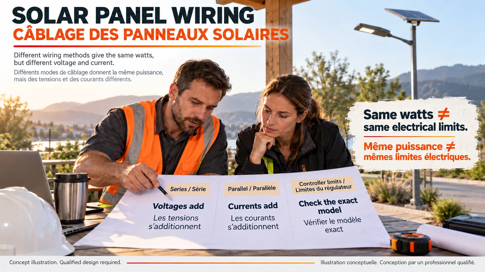
Solar panel wiring in series and parallel
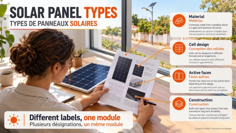
Series means joining the positive terminal of one module to the negative terminal of the next to form a string. Parallel means joining positive branches together and negative branches together. Those are circuit definitions, not a recommendation to assemble a particular installation. Renogy’s solar panel wiring guide illustrates the basic distinction; approval still depends on the complete equipment combination.
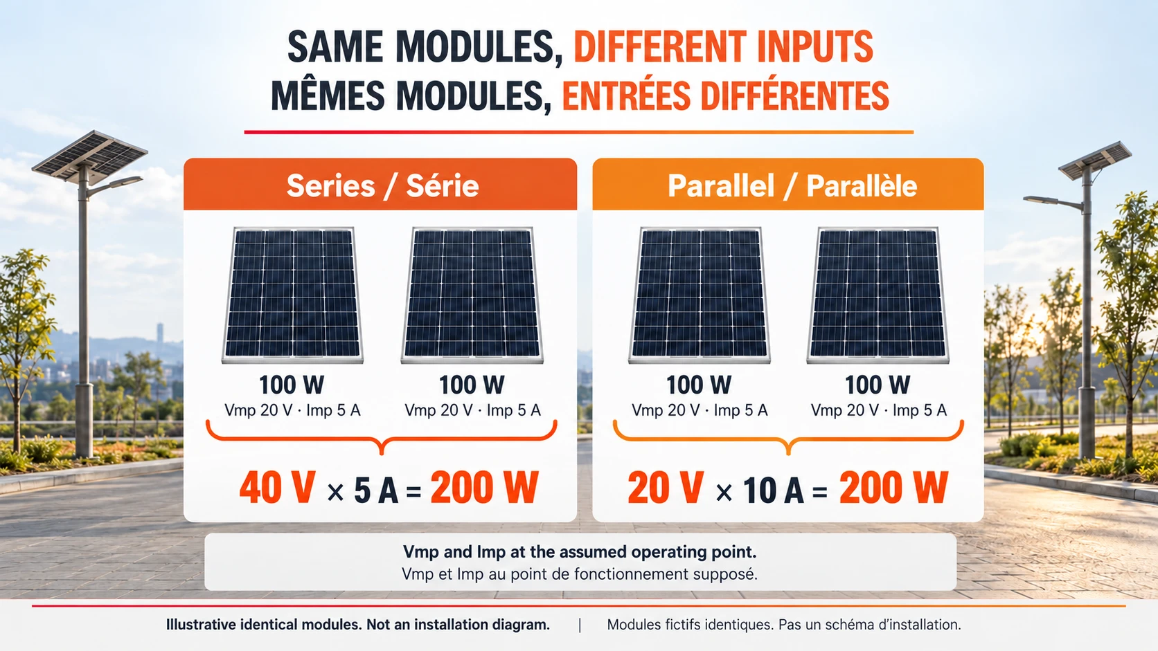
For identical modules under the same conditions, series raises the string voltage while the current stays at the single-module value. Parallel keeps the module voltage while the branch currents add. A series-parallel array combines these principles. With unlike modules, uneven sunlight or different orientations, the simple arithmetic is only a starting point: the designer must assess mismatch and the actual operating point.
Same watts, different electrical inputs
Assume two identical 100 W modules. Each has Vmp 20 V, Imp 5 A, Voc 24 V and Isc 5.5 A at the stated reference conditions. Vmp and Imp describe the maximum-power operating point; Voc is open-circuit voltage and Isc is short-circuit current. They are different limits, not interchangeable ways to calculate usable power.
| Illustrative quantity | One module | Two in series | Two in parallel |
|---|---|---|---|
| Vmp | 20 V | 40 V | 20 V |
| Imp | 5 A | 5 A | 10 A |
| Pmp = Vmp × Imp | 100 W | 200 W | 200 W |
| Voc at the reference condition | 24 V | 48 V | 24 V |
| Isc at the reference condition | 5.5 A | 5.5 A | 11 A |
Both two-module arrangements total 200 W in this idealized example. Yet the controller sees either roughly 40 V at 5 A or 20 V at 10 A at the assumed operating point. That difference can determine whether the design is acceptable. Multiplying Voc by Isc would give 132 W per module here, but it would not be the module’s 100 W operating power: open circuit and short circuit are not simultaneous power-producing conditions.
A cold-voltage check can reject the series option
A controller’s maximum PV voltage must not be checked against Vmp alone. The Victron MPPT installation manual, PV array section explicitly requires consideration of Voc and its temperature coefficient when determining series length. Its own voltage and start-up requirements are model-specific; they are not universal settings for Inlux lights.
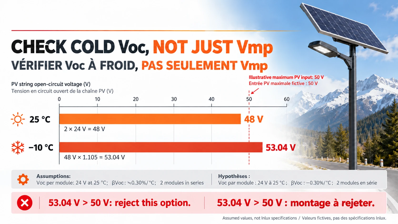
Continue the hypothetical example with Voc 24 V per module at 25 °C, a Voc temperature coefficient of −0.30%/°C, and an assumed minimum cell temperature of −10 °C. The temperature difference is −35 °C. Using the coefficient as −0.003/°C gives a factor of 1 + (−0.003 × −35) = 1.105. The two-module series Voc becomes 2 × 24 × 1.105 = 53.04 V.
If the hypothetical controller has a 50 V absolute maximum PV input, 48 V at the reference condition looks acceptable, but 53.04 V at the assumed cold condition is not. Reject that series option. Do not treat an absolute maximum as a target or assume that a controller will harmlessly limit an excessive input voltage. Real designs must use the module manufacturer’s method, applicable margins and site design temperatures.
Changing to parallel would reduce the illustrative cold Voc to 26.52 V, but that does not automatically approve the alternative. Its current is higher, and its operating voltage might not satisfy the selected controller’s start-up or tracking requirements. A failed series calculation is a reason to review the equipment combination, not permission to change wiring on site.
Check the whole controller envelope
| Check | Series/parallel consequence | Decision required |
|---|---|---|
| PV open-circuit voltage ceiling | Series increases Voc; cold conditions can raise it further | Temperature-corrected maximum remains within the permitted design envelope |
| Start-up and MPPT operating window | A lower-voltage parallel array may not provide enough input voltage | Check the exact controller requirements across the design conditions |
| PV input current and permitted Isc | Parallel branches add current | Check the applicable limits separately, including each input or tracker |
| Battery-side charging current | It is not automatically equal to PV-side current | Confirm charge conversion, battery limits and permitted array power |
| Cables, connectors and protection | Topology changes the duty of branches and combined paths | Approve the complete arrangement, not just a connector rating |
إن solar charge controller selection guide covers the device-level checks. Keep those checks beside the proposed array schedule rather than choosing a controller from a charging-current number alone. PV-side input limits and battery-side output limits describe different parts of the system.
A light quantity is not a PV string length
Among the published Inlux references, the Burkina Faso project reference records 1,095 lighting units. That is a procurement quantity, not a statement that 1,095 panels belong in one electrical string. The published quantity does not disclose a wiring schedule. Keep the number of lighting systems separate from the number of modules connected to any one controller.
| Lighting arrangement | Relevant wiring boundary | Do not infer |
|---|---|---|
| All-in-One — integrated lighting unit | The approved integrated light and its internal arrangement | That a buyer can add external panels to a sealed assembly |
| All-in-Two — separate-panel lighting unit | The separate PV panel and its approved lamp-head interface | That a separate panel authorizes arbitrary module combinations |
| Split Type — separated-component lighting unit | The PV, controller, battery and luminaire paths in the selected configuration | That all separately mounted components are interchangeable |
| Commercial parking project | Each standalone system or a specifically engineered shared arrangement | That the project’s equipment count defines a single PV array |
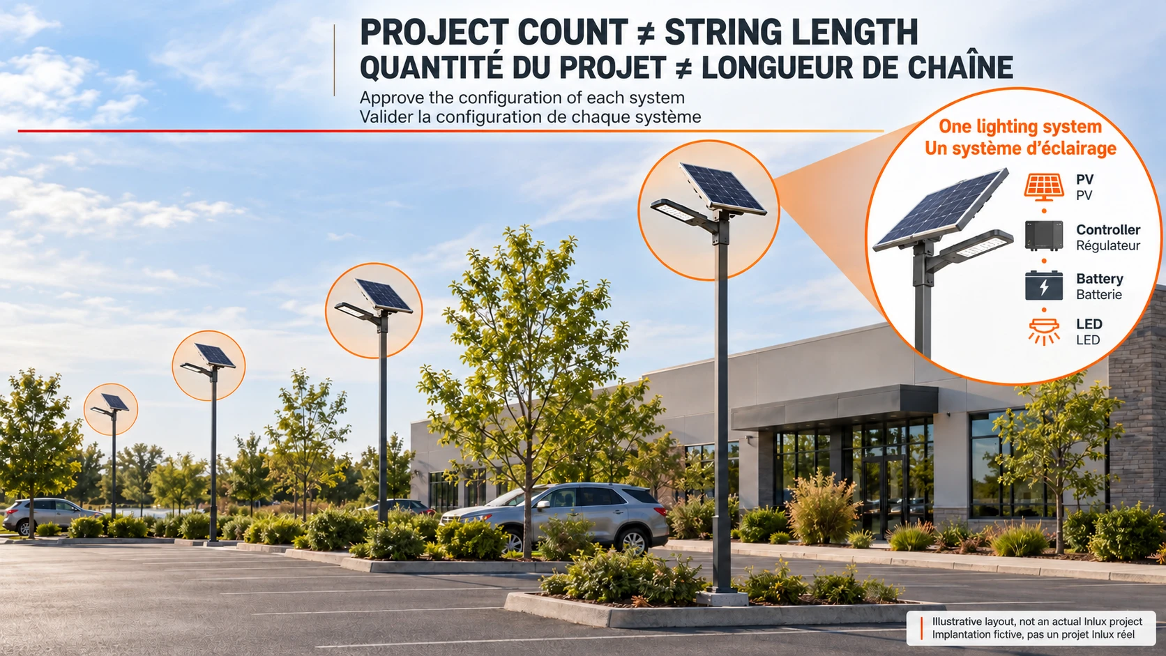
The integrated design is shown in the integrated All-in-One range. Separate PV mounting is shown in the separate-panel All-in-Two range. Fully separated components are described in the Split Type range. For commercial parking lighting, define the intended system boundary before comparing connection proposals. A central shared PV system is a different engineering scope from a set of standalone lights.
Cable and shading questions still need their own answers
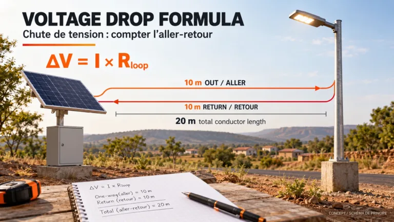
Series can reduce current for a given transmitted power, which can change cable loss. It does not make any cable size acceptable. Parallel can preserve a lower array voltage, but a combined conductor must carry the combined current. Use the DC voltage drop guide for the route calculation and the MC4 connector matching guide for the interface. Neither replaces conductor ampacity, protection or installation requirements.
Likewise, “parallel solves shade” is too broad. Shading response depends on the shaded area, module circuit, bypass diodes, the remaining string voltage and the tracker. Ask whether the proposed layout has been assessed for the actual obstruction and orientation. Do not promise a percentage gain merely because the quotation changes from series to parallel.
FAQ: solar panel wiring for lighting projects
Is it better to wire solar panels in series or parallel?
Neither is universally better. Series raises voltage; parallel raises current. Compare cold Voc, the controller’s operating window, applicable PV current limits and the complete installation. The same two modules can have equal nominal power in both arrangements but only one acceptable equipment combination.
Does a 12 V battery require a 12 V PV input?
Not necessarily. Battery-system voltage and PV input voltage are separate specifications. The permitted combination depends on the controller’s conversion method and limits. Do not read a battery-voltage label as the maximum PV voltage, and do not assume every controller accepts a higher-voltage string.
Why can a panel string exceed its stated Voc in cold weather?
The reference Voc is tied to stated test conditions. A negative Voc temperature coefficient means the voltage rises as cell temperature falls. The designer must apply the module’s coefficient and required calculation method to the site conditions, rather than approving a series string from its reference voltage alone.
What wire size is best for solar panel wiring?
There is no universal size. The design must account for current, route length, voltage drop, insulation rating, temperature, installation method and protection. Specify conductor area and the complete cable type; a connector’s permitted cable range or a generic online chart does not approve the circuit.
Can I add another panel to an existing solar street light?
Only if the equipment supplier approves that exact modification and qualified personnel implement the approved design. Extra PV watts can change voltage, current, mechanical loading, cable duty and charge behaviour. A spare connector or a separate panel does not establish expandability.
Can this article be used as an installation wiring diagram?
No. The examples explain how to compare configurations. Actual installation needs the correct model documentation, design approvals and site safety procedures. Do not copy a generic energisation order or use the illustrative 50 V controller limit as a setting for real equipment.
Ask for the complete configuration, not just more PV watts
To shortlist an equipment architecture, browse the Inlux solar street light range, then request a project-specific configuration review. Include the site, lighting task, proposed module and controller references, and whether this is new equipment or a replacement. Ask the quotation to state the approved PV arrangement and system boundary. That is a useful purchasing decision; an unexplained “200 W panel system” is not.