






A camera pole is a support structure for surveillance equipment, but selecting one requires more than a height and material. For solar street-lighting and parking projects, check the viewing task, structural approval, mounting interfaces, image stability, power supply and acceptance plan together. A bracket that fits around a pole does not prove that the complete installation is suitable.
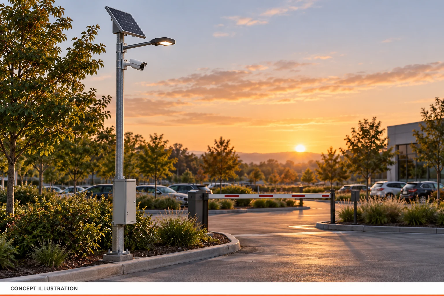
This guide helps project buyers decide between a dedicated camera pole and an approved shared lighting pole. It is not a guide to attaching equipment to public infrastructure or modifying a pole without permission. Keep the existing solar CCTV system proposal as the route for complete off-grid power and surveillance integration; the decisions below concern the support and installation interface.
1. Define the view before specifying the camera pole height
Describe what must be visible and where: general activity in a yard, a gate approach, a loading area or a particular access point. Mark the target areas, likely obstructions and intended camera positions on a site plan. Then ask the security integrator to confirm the camera, lens, viewing angle and mounting height that achieve that task.
Higher is not automatically better. Raising the camera changes the viewing geometry and may require a different lens or position. A broad overview and a close view of a specific target are different requirements. Do not copy the height of the nearest street light without checking the required image at that location.
Keep pole height, camera mounting height and the position of every other attachment as separate drawing dimensions. A camera placed below a solar panel may have a clear view in one direction and an obstruction in another. Review the working view and, for moving cameras, the intended movement envelope before approving the layout.
2. Decide whether an existing lighting pole can be reused
Reuse is a candidate, not an automatic saving. First identify the pole owner, drawing or asset reference, condition and permission to attach equipment. The responsible engineer must review the added camera, arm, enclosure, panel and other loads together with the existing installation. An unknown pole history or missing structural basis is a reason to resolve the information gap, not to assume spare capacity.
A dedicated camera pole can place surveillance where it is needed without tying the camera location to the lighting layout. A shared pole may reduce the number of structures, but combines maintenance access, equipment interfaces and responsibilities. Compare the installed and maintained arrangement, not only the purchase price of the bare pole.
For the structural quotation, use the commercial light pole requirements. For the civil interface, the light pole base procurement guide separates foundation responsibility from pole supply. This camera guide does not prescribe foundation dimensions or approve a retrofit. Do not drill, weld or change a pole on the strength of a generic online instruction.
3. Match the entire mounting chain

Check each interface: pole to saddle or bracket, bracket to arm, arm to camera adapter, and adapter to the exact camera. Record the part references, pole section at the mounting position, attachment method and required accessories. A camera-body photograph cannot establish the correct fixing pattern, thread or load rating.
A useful manufacturer example is the AXIS T91B47 pole mount, offered in versions for 50–150 mm and 100–410 mm pole diameters. These are ranges for that named accessory, not universal pole dimensions or evidence of compatibility with an Inlux arrangement. The example shows why the selected version and its supported equipment matter.
Treat a tapered pole differently from a constant-section assumption: the size at the actual attachment position is the relevant interface. Confirm material contact, finish protection, cable entry and service access using the approved assembly instructions. Do not invent tightening values, substitute straps by appearance or assume a clamp removes the need for structural review.
4. Separate structural adequacy from image stability
A pole can be structurally acceptable while the delivered video is still unsuitable for its task. Camera movement, the mounting arrangement and the operating view must therefore be reviewed as a performance question as well as an engineering question. A generic wind-speed statement is not an image-quality guarantee.
Technical context is provided in the Axis image-stabilization white paper, which describes vibration effects on high-pole cameras and the increased sensitivity of long-zoom views. Stabilization can help, but it is not a substitute for a suitable support and an agreed demonstration. Ask the integrator to check the selected camera in its intended operating view, not only a wide-angle image taken on a calm day.
Agree what useful video means before ordering. Identify the target area, camera settings, day and night conditions, permitted operating views and representative site conditions for acceptance. Record the result with the configuration used. Avoid unverified claims such as zero vibration or guaranteed recognition at every distance; the project team must define and demonstrate the required outcome.
5. Confirm power and maintenance without borrowing the lighting reserve
Mechanical reuse does not establish electrical compatibility. A solar lighting system may have been sized for its own operating schedule, not a camera and communications equipment running all day. Confirm supply voltage, interface, peak demand and daily energy for every added device before approving a shared supply.
For a simplified calculation only, a constant 12 W auxiliary load operating for 24 h uses 288 Wh per day: 12 W × 24 h = 288 Wh. This is not a proposed camera specification or battery size. Real sizing must include the actual operating modes, conversion losses, reserve and site conditions. Do not allocate existing lighting autonomy to an added camera without recalculating the system.
Also decide how technicians will reach the camera and enclosure, isolate relevant equipment and maintain the lighting service. Access equipment, safe work areas and responsibilities can affect lifecycle cost more than a small difference in pole price. Procedures must come from the responsible site team and equipment suppliers; this guide is not a work-at-height or electrical installation method.
6. Put separate acceptance decisions in the purchase order
Use a short responsibility matrix so a successful mechanical inspection does not silently become acceptance of the video, power or communications system. The following is a procurement structure to adapt, not a certification checklist or a replacement for local requirements.
| Acceptance decision | Evidence to agree | Responsible interface |
|---|---|---|
| Pole and foundation | Approved configuration, loads and civil design scope | Structural designer and pole supplier |
| Mounting chain | Compatible parts and assembly instructions | Camera integrator and mounting supplier |
| Useful video | Defined views and recorded day/night acceptance results | Security integrator and project owner |
| Power and connectivity | Approved load basis and agreed functional checks | Power/network integrator |
| Maintenance handover | Access method, asset references and service responsibilities | Installer and site operator |
Keep the as-supplied equipment list and accepted settings with the pole asset record. If the camera, lens, arm, panel or enclosure changes later, route the change back to the relevant reviewer. A replacement that powers on is not automatically equivalent in mounting, load or video performance.
Frequently asked questions
What is a camera pole used for?
It supports surveillance equipment at a position selected for the required view. The purchase may be a bare support, a pole with mounting hardware or a complete powered system. Identify that scope explicitly so cameras, connectivity, civil work and acceptance are not assumed to be included.
Can a security camera be mounted on an existing street-light pole?
Possibly, after owner permission, condition review, structural approval and confirmation of mounting and electrical interfaces. A clamp fitting the shaft is not sufficient evidence. Keep the original lighting requirements intact and do not make unapproved holes, welds or supply changes.
What height should a camera pole be?
There is no universal height. Select the viewing task, camera and lens, then check the location, obstructions and maintenance requirements. Confirm the camera mounting height separately from overall pole height and verify the resulting image before accepting the configuration.
Does image stabilization make any pole suitable?
No. Stabilization is a camera capability, not approval of the pole, foundation or bracket. It must be considered with the support arrangement and intended operating view. Acceptance should demonstrate useful video under the conditions agreed for the project.
Can a solar street light power an added camera?
Only if the complete power arrangement is approved for the additional demand and operating schedule. Confirm all devices and recalculate daily energy and reserve. Existing battery capacity or an unused connector does not establish permission or sufficient capacity for the added equipment.
What should a camera-pole RFQ include?
Provide the site plan, viewing task, camera and accessory references, proposed mounting positions, attachment loads, existing-pole records if relevant, power/connectivity scope and acceptance responsibilities. State what is supplied by others and what still requires engineering confirmation.
Coordinate the camera pole with the lighting proposal
Inlux Solar has delivered 1,000+ projects across 60+ countries. These company totals are not evidence that a particular pole or camera configuration has been tested. Inlux supplies solar power, poles and security-lighting integration; the existing system page distinguishes that role from manufacturing cameras.
To request a coordinated solar parking-area lighting project, submit the lighting and surveillance requirements together through the Inlux camera-pole configuration enquiry. Request a clear reuse-versus-new-support decision and agreed supply boundaries. Compatibility, standalone supply and performance remain subject to the specific proposal, not this general guide.