






Quick answer: A solar charge controller regulates the electricity moving from a photovoltaic panel to a rechargeable battery and, in many off-grid systems, to a DC load. It applies a battery-compatible charging profile, limits unsafe operating conditions and may manage low-voltage disconnect, dusk-to-dawn switching, dimming and data logging. Choose one by checking the complete voltage, current, battery, load, temperature and control requirements—not by matching “12 V” or an amp rating alone.
For a solar street light, the controller is the operating link between daytime energy collection and nighttime lighting. A weak match can leave a correctly sized panel and battery unable to perform as intended. A good specification therefore records the controller model, firmware or setting profile, PV limits, battery chemistry, load capability, lighting schedule and environmental enclosure as one coordinated configuration.
What is a solar charge controller?
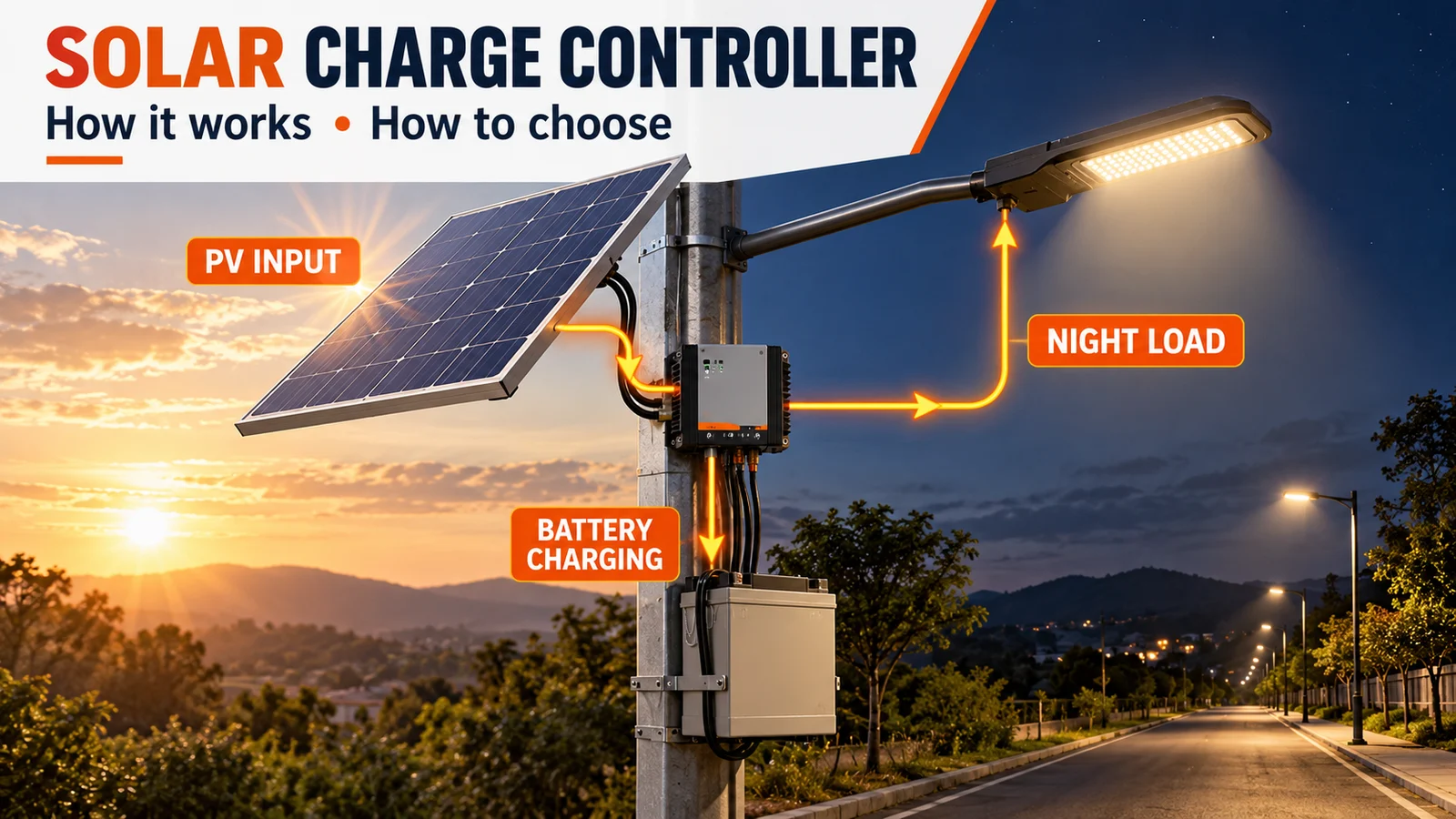
A solar charge controller is an electronic regulator used between a PV source and a battery-based DC system. During daylight, it controls charging as panel voltage, irradiance, battery voltage and temperature change. When solar input falls, it prevents unwanted reverse current and may switch or regulate the connected load.
The U.S. Department of Energy’s foundational solar course describes an off-grid PV arrangement in which power passes through a charge controller before reaching battery storage and a DC load or inverter. That is a useful system boundary, but each manufacturer’s circuit, ratings and software behaviour remain product-specific.
The controller sits inside a larger system:
Sunlight → PV module → controller → battery → LED driver/load
That simple arrow hides several separate design questions. The PV module must stay within the controller’s input window. The battery must receive the correct charge profile. The load must not exceed the load-output capability. The nightly energy schedule must fit the energy collected and stored. Our how solar lights work guide explains the complete day-to-night cycle.
What does a solar charge controller do?
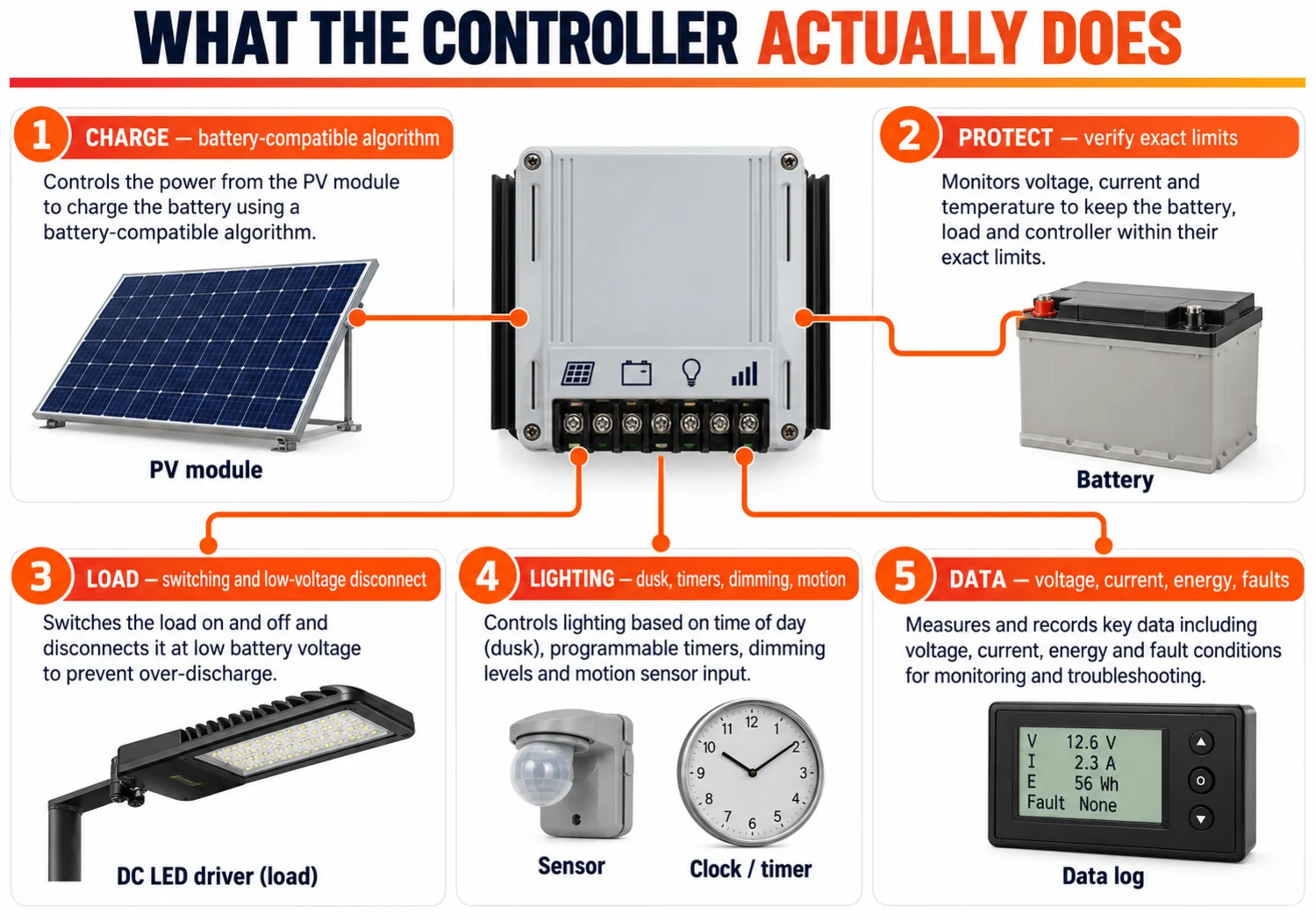
Depending on the model, one device may perform some or all of these functions.
Regulate battery charging
The controller adjusts voltage and current according to a defined charge algorithm. Lead-acid systems may use bulk, absorption and float behaviour, with equalisation only where the battery manufacturer permits it. Lithium systems normally require a battery-specific profile coordinated with the battery-management system. The names of stages are less important than using the settings approved for the exact battery.
Protect against operating limits
Possible protections include reverse-current blocking at night, PV reverse-polarity protection, battery reverse-polarity protection, output short-circuit protection, over-temperature protection and high- or low-voltage limits. Never assume every controller provides every protection. Confirm the datasheet, wiring diagram and certification scope.
Control the DC load
Some controllers have a dedicated load output and low-voltage disconnect. The load can be switched off before the battery reaches a damaging state. Load current is a separate rating from charge current: a 20 A charging label does not automatically mean the load terminal can drive any 20 A load.
Run the lighting schedule
Lighting controllers may detect dusk from PV voltage or a separate sensor, then apply timed output levels, motion-triggered boost, morning operation or seasonal schedules. In a solar street light, this function determines how much energy the LED uses during each part of the night. The controller schedule must match the assumptions in the solar street-light battery-sizing calculation.
Record faults and operating data
More capable models can report PV voltage/current, battery voltage, charging state, load state, energy totals, temperature and fault codes. Remote data is useful only if timestamps, units, sensor location and firmware configuration are recorded. A screenshot without the controller identity or operating mode is weak diagnostic evidence.
What it does not replace
A controller is frequently confused with four other components.
| Component | Primary job | Why it is not the controller |
|---|---|---|
| Battery-management system (BMS) | Protect and balance cells inside a battery pack | It does not normally replace the external PV charging algorithm or system load schedule |
| LED driver | Regulate electrical power delivered to the LED module | It controls the light source, not necessarily PV-to-battery charging |
| Inverter | Convert DC electricity to AC | A stand-alone DC light often has no inverter at all |
| Fuse, breaker or disconnect | Isolate faults and allow safe service | Electronic protection is not a substitute for required overcurrent protection and isolation |
Some products combine several functions in one enclosure. That does not make the terms interchangeable. The MPPT solar inverter guide explains the boundary between maximum-power-point tracking, battery charging and DC-to-AC conversion.
How a solar charge controller works from day to night
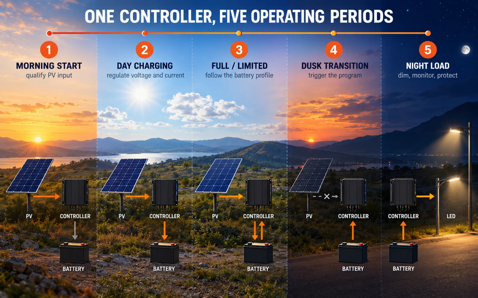
The exact state machine is manufacturer-specific, but a practical review can follow five operating periods.
- Morning start: PV voltage rises. The controller checks whether solar input is usable and begins charging under its programmed limits.
- Daytime charging: Available PV power and battery acceptance change with sunlight, temperature and state of charge. The controller moves through the configured charging behaviour.
- Full or limited charging: Charging current is reduced or managed when the battery reaches its programmed threshold. Connected loads may continue to operate if the architecture permits.
- Dusk transition: Falling PV input or a separate sensor triggers the lighting schedule after any programmed delay.
- Night operation: The battery supplies the DC load. The controller may dim, boost after motion, record energy use and disconnect the load at a defined low-voltage condition.
The U.S. Department of Energy explains that solar plus storage separates when energy is produced from when it is used. A street-light controller turns that principle into an operating schedule, but it cannot create energy that the panel did not harvest or the battery cannot store.
PWM versus MPPT: choose by the system, not the acronym
PWM and MPPT controllers solve the same broad task with different electrical approaches.
- A PWM controller connects and switches the PV source in a way that pulls its operating voltage toward the battery charging voltage. It can be practical when the array and battery are closely matched and the project values simplicity.
- An MPPT controller uses power electronics and an algorithm to operate the PV array near a maximum-power point, then converts that input to a suitable battery-charging output. It provides more flexibility when array voltage is meaningfully above battery voltage or conditions vary.
MPPT is not automatically the correct answer for every light, and PWM is not automatically low quality. The decision depends on module voltage, temperature range, cable length, energy margin, battery architecture, controller self-consumption, load/control functions, price and maintainability. Use the existing MPPT versus PWM guide for solar street lights for the detailed comparison; this page keeps the broader controller-selection task separate.
Eight checks before selecting a solar charge controller
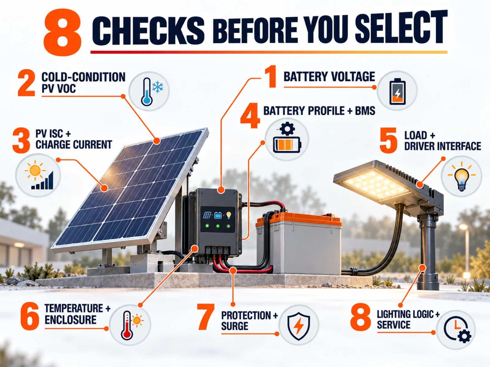
1. Battery-system voltage
Confirm the nominal battery voltage and the controller’s supported range. “12/24 V auto” is not enough if the system uses a different nominal voltage, a lithium profile that requires manual selection, or a deeply discharged battery that can confuse automatic detection. Record how the initial voltage is set and how it is restored after service.
2. Maximum PV open-circuit voltage
Add the open-circuit voltage of modules in series, then correct it for the lowest expected cell temperature using the module manufacturer’s coefficient and design method. Cold modules can produce a higher open-circuit voltage than the standard-test-condition value. The result must remain below the controller’s absolute input limit with the required design margin.
Victron’s official MPPT installation guidance tells users to keep maximum PV open-circuit voltage below the relevant model limit and points to a sizing calculator. The example limits belong to those specific products; copy the method, not another model’s number.
3. PV short-circuit current and charging current
Check both the allowable PV short-circuit current and maximum battery charge current. They are not interchangeable. Use module Isc, parallel string count, temperature or irradiance assumptions, controller rules and applicable electrical requirements. Also confirm whether the controller intentionally clips excess array power and under what thermal conditions.
4. Battery chemistry and charge profile
Obtain the battery manufacturer’s approved charge voltage, current, temperature limits, low-temperature charging rule and communication requirements. Confirm whether equalisation is disabled for batteries that do not permit it. For LiFePO4, check coordination between the controller and BMS after a BMS disconnect or recovery event. Our solar street-light battery comparison explains why chemistry and project conditions must be evaluated together.
5. Load output and LED-driver interface
Record normal current, inrush, dimming signal, switching method and maximum load-terminal rating. A solar lighting controller may have an integrated LED driver, a separate driver output or only a relay/control signal. The wiring and protection strategy changes with that architecture.
6. Temperature and enclosure
Check full operating range, derating curve, cooling clearance, humidity, condensation, ingress protection, corrosion environment and installation location. A controller rated for an indoor enclosure should not be treated as weatherproof because the finished luminaire has a separate IP rating.
7. Protection and surge coordination
Verify polarity, over-temperature, short-circuit and overvoltage behaviour, but do not treat internal electronics as the complete project protection system. Cable routing, grounding, bonding, external overcurrent devices and surge protective devices still require coordinated design. See the solar street-light surge-protection guide for the system boundary.
8. Lighting logic, data and serviceability
Specify dusk threshold or sensor method, time delays, dimming steps, motion logic, low-voltage response, data retention, clock behaviour, communications, firmware control and replacement procedure. A spare controller is not truly interchangeable unless connectors, polarity, settings, load interface and firmware behaviour match.
A preliminary solar charge controller sizing example
Consider a fictional 24 V battery system with a 180 W PV module. Dividing rated PV power by nominal battery voltage gives a first-pass charging-current scale:
180 W ÷ 24 V = 7.5 A
That calculation does not prove that an 8 A or 10 A controller is suitable. Final selection still requires:
- module Voc corrected for the coldest design condition;
- module Isc and any required current margin;
- controller conversion and clipping rules;
- maximum permitted battery charge current;
- load-terminal current and LED-driver behaviour;
- temperature derating inside the enclosure;
- cable, fuse, disconnect and surge design;
- controller self-consumption and standby behaviour.
If two modules are placed in series, voltage changes while string current does not double. If they are placed in parallel, current increases while string voltage stays similar. The chosen arrangement must fit all controller input limits, not just the headline wattage.
This is an instructional example, not an Inlux product configuration or a universal sizing rule. Use the exact panel, battery, controller and site-temperature data for the project.
Three calculations to place beside the controller datasheet
One current estimate is not enough. A procurement review should show at least these three checks in the same worksheet. The values below are fictional and illustrate method only.
| Check | Example calculation | What the reviewer still has to verify |
|---|---|---|
| PV charging-current scale | 180 W ÷ 24 V = 7.5 A |
Actual conversion behaviour, charge-current limit, module Isc, temperature and design margin |
| Nightly LED energy | (60 W × 4 h) + (30 W × 6 h) = 420 Wh |
Driver input power rather than LED nameplate watts, seasonal night length, losses and reserve |
| DC load-current scale | 60 W ÷ 24 V = 2.5 A |
Driver efficiency, startup inrush, cable drop and the controller’s separate load-terminal limit |
The energy line is especially useful for dimming schedules. In this example, running 60 W for the full 10-hour night would consume 600 Wh; the two-stage schedule uses 420 Wh, a difference of 180 Wh before driver and wiring losses. That difference belongs in the battery and PV energy budget. It does not increase the controller’s permissible voltage or current.
Array connection must be shown just as explicitly. Two identical modules wired in series produce approximately 2 × Voc and 1 × Isc; two wired in parallel produce approximately 1 × Voc and 2 × Isc. Use the module’s temperature coefficients and the controller manufacturer’s sizing procedure for the final maximum and minimum values.
A fictional cold-voltage check shows why the datasheet values matter. Assume one module has Voc = 45.0 V at the 25°C standard-test condition, its Voc temperature coefficient is -0.28%/°C, and the design cell temperature is -10°C. The temperature difference is 35°C; the approximate voltage increase is 35 × 0.28% = 9.8%, giving 45.0 × 1.098 = 49.4 V per module. Two in series would therefore be about 98.8 V before any additional code- or manufacturer-required margin. Do not reuse these fictional values: obtain the exact coefficient, temperature basis and permitted calculation method for the selected module and controller.
Solar charge controller settings: never copy a voltage table blindly
Battery settings are configuration data, not generic blog values. A voltage that is appropriate for one cell count or lead-acid type can damage or undercharge another battery.
The current Victron configuration and settings manual warns that incorrect settings may damage batteries and offers predefined or user-defined charge algorithms. This is a useful review principle across brands: obtain the battery recommendation first, then document the controller profile that implements it.
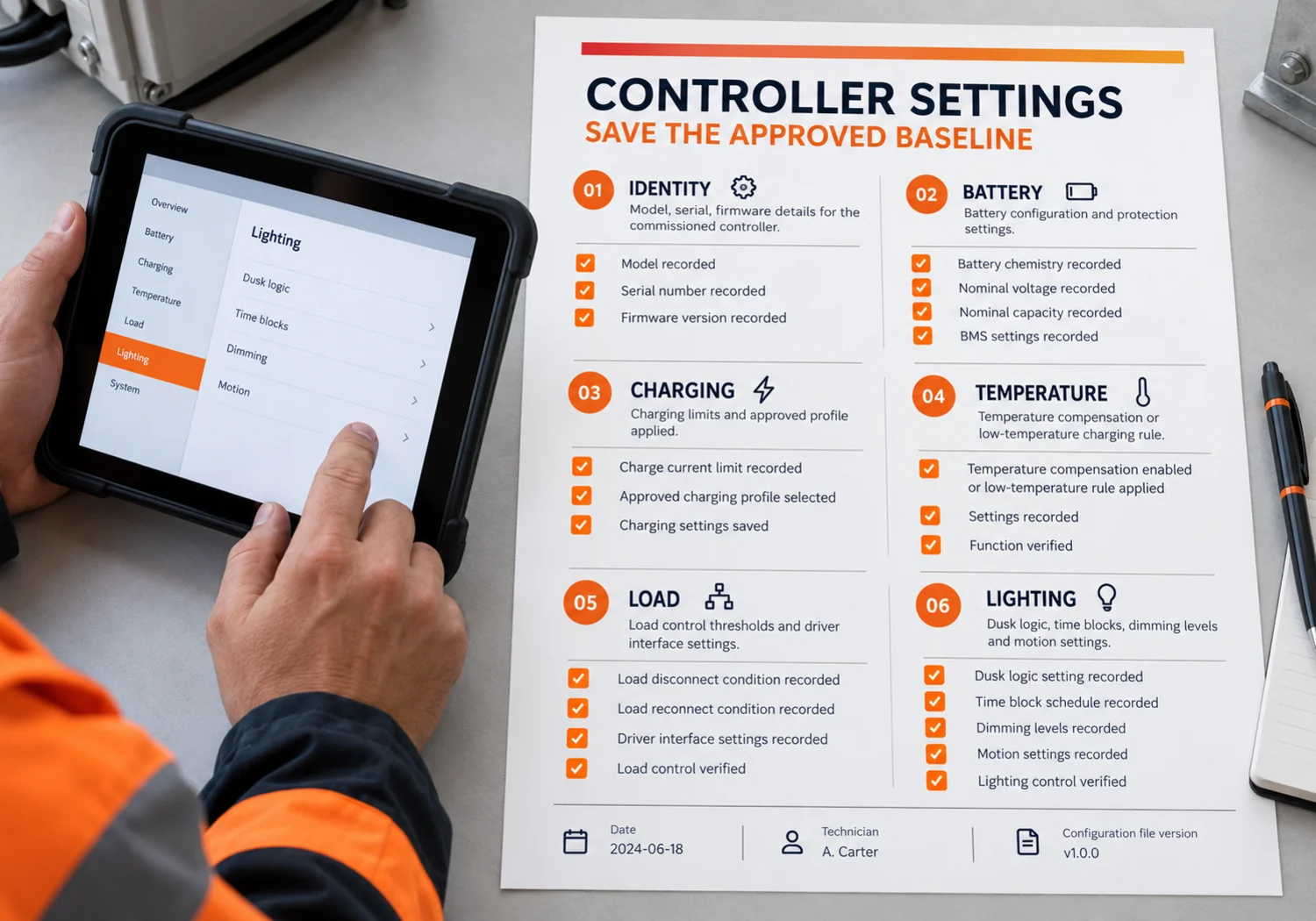
At commissioning, record at least:
- controller manufacturer, model, serial number and firmware;
- nominal battery voltage and detected/configured voltage;
- battery chemistry, cell count, capacity and BMS identity;
- charge-current limit;
- absorption, float or equivalent profile settings where applicable;
- equalisation status and permission;
- temperature compensation or low-temperature charge control;
- load disconnect and reconnect thresholds;
- dusk/dawn logic, dimming timetable and sensor actions;
- date, technician and approved configuration-file version.
What is different in a solar street light?
A general off-grid solar charge controller may only manage PV charging and a simple DC load. A street-light controller often has to coordinate five tasks at once: battery charging, dusk detection, timed dimming, LED output and low-energy protection. Some systems add motion sensing or remote monitoring.
That makes three documents inseparable:
- Energy calculation: Can the panel and battery support the programmed watt-hours through the design night and autonomy period?
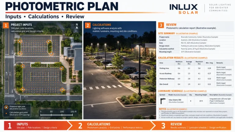
- Photometric calculation: Does each output level place enough light in the required area with acceptable uniformity and glare?
- Controller schedule: Does the installed firmware actually command the output levels used by the two calculations?
A report that says “30% after midnight” is incomplete unless 30% maps to a known electrical input and photometric output. A controller change after approval can invalidate both the energy budget and lighting model even if the replacement has the same nominal voltage.
Inlux Solar has delivered more than 300,000 lighting units across 60+ countries. That experience does not make one setting universal; it supports documenting location, operating profile, component identity and acceptance conditions for each project. Explore the commercial solar street-light systems and the complete pole-and-battery project guide for the wider system context.
Procurement specification: fields that must be explicit
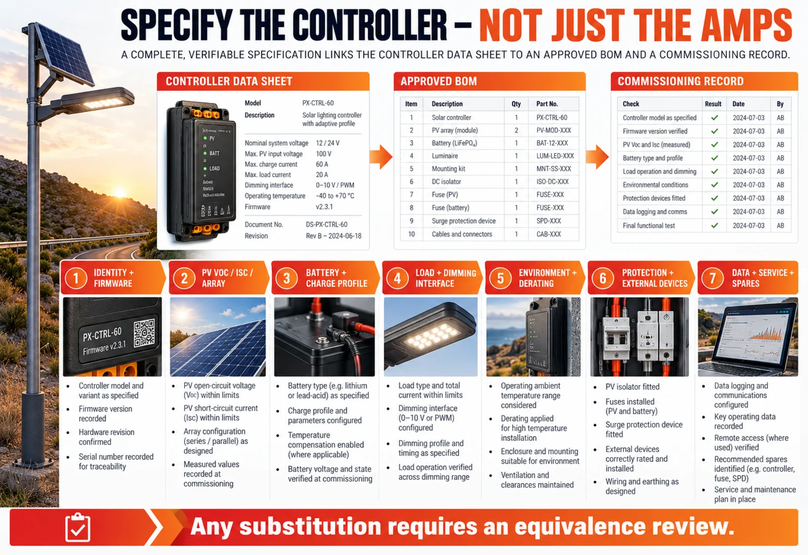
| Field | What to specify | Weak substitute to reject |
|---|---|---|
| Controller identity | Manufacturer, model, hardware revision and firmware | “Smart controller” |
| PV input | Maximum Voc at cold condition, Isc, array configuration and power rules | Panel watts only |
| Battery | Chemistry, nominal voltage, capacity, BMS and approved profile | “Lithium compatible” |
| Charging | Maximum current, algorithm, configurable limits and temperature behaviour | Amp label only |
| Load | Rated/peak current, driver interface, dimming method and disconnect logic | LED watts only |
| Lighting program | Dusk method, time blocks, output levels, motion and morning mode | “Auto on/off” |
| Environment | Operating/derating range, enclosure/IP boundary, humidity and corrosion | Outdoor grade |
| Protection | Internal protection plus external fuse, disconnect, grounding and SPD scope | “Full protection” |
| Data | Logged variables, timestamp, retention, access and communications | App supported |
| Evidence | Datasheet, manual, wiring drawing, setting file, test/certification scope | Product photo |
| Service | Connector/polarity map, replacement process, password/firmware ownership and spares | Same voltage replacement |
Put these solar charge controller fields into the approved BOM and commissioning record. If the supplier changes the controller, require a documented equivalence review covering every affected field—not just cost and amp rating.
Troubleshooting without replacing parts at random
| Symptom | Possible controller-related causes | First checks |
|---|---|---|
| Battery does not charge | PV input below start condition, reversed/open connection, input limit event, wrong profile or controller fault | Measure PV and battery voltage safely; read status/fault log; verify disconnects and polarity |
| Light stops early | Energy deficit, load schedule too high, low-voltage disconnect, battery capacity loss or temperature effect | Compare daily charge, battery state, programmed profile and actual load watt-hours |
| Light stays on in daytime | Dusk input covered, PV sensing issue, timer/clock error or control output fault | Check sensor exposure, PV status, time and operating mode |
| Repeated on/off cycling | Battery voltage recovery around thresholds, loose connection, driver inrush or thermal protection | Review event log and voltage under load; inspect connectors and temperature |
| Controller is hot or derating | Enclosure temperature, blocked cooling, excessive current or unsuitable installation | Compare measured conditions with the model’s derating and mounting requirements |
| New controller behaves differently | Wrong battery profile, firmware, polarity, load mode or dimming map | Compare the approved setting record and exact wiring/interface |
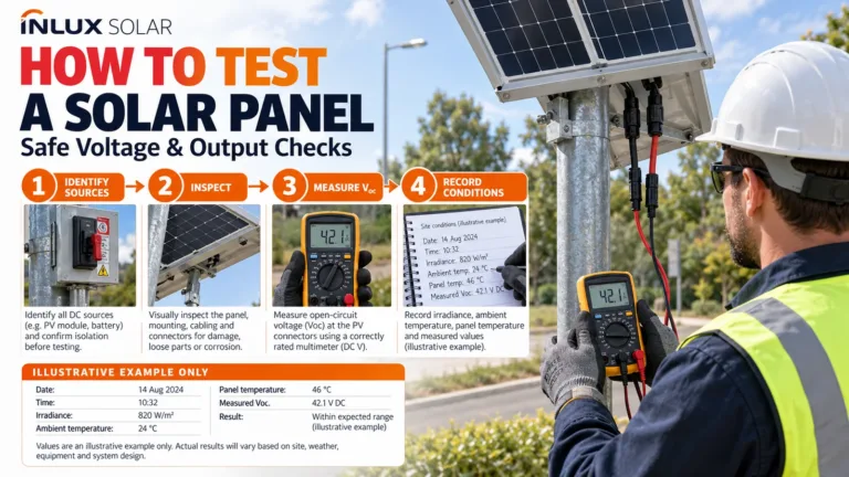
Electrical measurements and solar charge controller wiring changes should be performed by qualified personnel following the product manual and local rules. Preserve logs and settings before a reset. Replacing the battery first can hide a charging or schedule problem until the new battery also loses capacity.
If you need a project configuration review, send the PV module datasheet, battery specification, controller model, load/driver data, project coordinates, nightly schedule, autonomy target and quantity through the Inlux Solar project enquiry page. A useful response should return a traceable component schedule and settings basis, not only a controller amp rating.
Frequently Asked Questions
Do I need a solar charge controller for every solar panel?
Not for every PV application. Battery-based off-grid systems normally require controlled charging, while a grid-connected architecture may perform power conversion through other equipment. Follow the system design and equipment instructions rather than connecting a panel directly to a rechargeable battery.
Is an MPPT controller always better than PWM?
No. MPPT can recover more available PV power and allows more array-voltage flexibility in many systems, but cost, self-consumption, module/battery matching, climate, load controls and maintainability also matter. Compare the complete design rather than one efficiency claim.
How many amps should my controller be?
Calculate from the actual PV array and battery architecture, then check the controller’s PV short-circuit-current limit, maximum charge current, load current, temperature derating and manufacturer sizing rules. Panel watts divided by battery voltage is only a preliminary scale, not a final rating.
Can one controller work with LiFePO4 and lead-acid batteries?
Some models provide multiple battery presets or programmable profiles, but compatibility must be confirmed for the exact battery, cell count, BMS and temperature limits. Changing chemistry requires reviewing settings; it is not only a menu-label change.
Is a solar controller the same as an inverter?
No. A charge controller regulates PV-to-battery charging and may control DC loads. An inverter converts DC to AC. Hybrid equipment can combine both functions, so confirm the internal architecture and ratings rather than relying on the enclosure name.
Why does a solar street light controller need a dimming schedule?
The schedule controls nightly energy use. It can preserve battery reserve by reducing output during low-activity periods and increasing it when required. Every programmed level should be reflected in the energy calculation and, where lighting compliance matters, the photometric calculation.