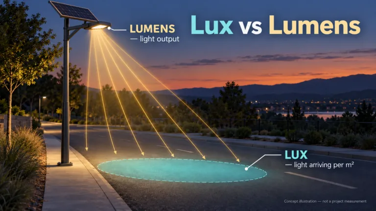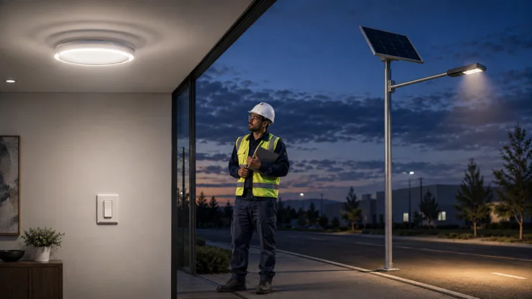







Quick Answer: Solar street light acceptance testing should be treated as a field verification procedure after installation, not as a pole-spacing design tutorial, an IES/DIALux input guide, or a commissioning paperwork checklist. The purpose is to confirm whether the installed lighting system delivers the required on-site illuminance, overall uniformity, and acceptable glare control under real nighttime operating conditions.
In practical project handover, three questions matter most: Are the lux readings on the pavement within the expected range? Is the light distributed evenly enough across the road surface? And does the installation avoid obvious glare risks caused by tilt, aiming, mounting height, or optical mismatch? This guide focuses on those field-verification questions.
If your goal is to check installation records, serial mapping, controller settings, and handover documentation, see our Solar Street Light Installation & Commissioning Checklist. If your goal is to request photometric files, simulation deliverables, or RFQ clauses before procurement, use our IES & DIALux Resource Center.
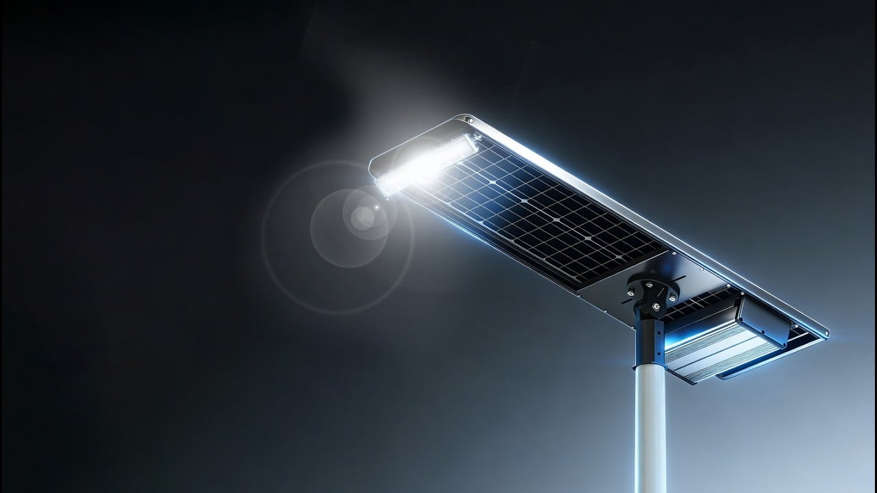
Video: Field overview of solar street light acceptance testing for illuminance, uniformity, and glare verification.
What this guide covers — and what it does not
This page is specifically about field acceptance testing after installation. It covers how to measure road-surface illuminance, how to calculate overall uniformity from measured points, how to assess practical glare risk on site, and how to investigate a mismatch between measured results and the approved lighting design report.
It does not replace a pole spacing design guide, a beam-angle specification guide, or a commissioning handover checklist. Those topics should remain separate so the acceptance process stays clear and auditable.
Why acceptance testing matters in solar street light projects
Acceptance testing is the final technical checkpoint between installation and project sign-off. It confirms whether the installed solar street light system performs in the real environment as intended in the approved design package. For municipal roads, factory roads, communities, campuses, and infrastructure sites, that means comparing field results against the design basis rather than relying on brochure claims or wattage labels.
A standardized acceptance workflow helps project teams:
- verify that actual lighting performance is consistent with the approved design basis;
- identify dark zones, aiming errors, spacing-related weak spots, or optical mismatch;
- create traceable records for consultants, EPC teams, municipalities, and donors;
- reduce disputes during handover by using repeatable, evidence-based measurements.
Core acceptance items to verify on site
For most road and area-lighting projects, field acceptance should focus on the following items:
- Illuminance: Does the road surface receive the expected light level in the tested area?
- Overall uniformity: Is the light distributed evenly enough, without obvious bright-hotspot and dark-gap behavior?
- Glare risk: Does the installed fixture create uncomfortable or visibility-reducing glare because of incorrect tilt, aiming, or mounting geometry?
- Installation consistency: Do pole height, luminaire angle, outreach, spacing, and orientation match the approved layout?
- Operating condition: Is the system tested under a stable and representative nighttime operating state?
Required tools and documents
| Item | Purpose | Practical note |
|---|---|---|
| Calibrated lux meter | Measure road-surface illuminance at each test point | Use a meter suitable for low-light outdoor field work |
| Tape measure or laser distance meter | Lay out the field grid accurately | Use consistent geometry across the entire test zone |
| Site test sheet or digital log | Record measured values and field conditions | Every point should be traceable |
| Approved lighting design report | Provide the comparison baseline | Use the approved version, not a draft or sales sample |
| Project layout drawing | Verify installation geometry | Check spacing, mounting height, and arrangement type |
Pre-test conditions you should confirm first
Before taking any measurement, confirm that the test conditions are stable enough for comparison with the design report.
- The battery should be adequately charged for normal nighttime output.
- The luminaires should be operating normally and allowed to stabilize before the reading session.
- Testing should be carried out at night under dry and stable weather conditions.
- The road surface should be dry and reasonably clear of temporary obstructions.
- The tested operating mode should match the project’s intended handover mode.
Step 1: Confirm the design basis before laying out the grid
This is the most common source of false acceptance disputes. If the site team measures one geometry while the design report assumed another, the numbers are no longer comparable.
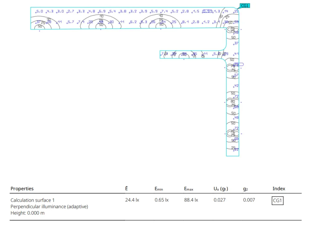
Before marking test points, verify the following against the approved design documentation:
- road width and lane arrangement;
- pole height and outreach;
- pole spacing;
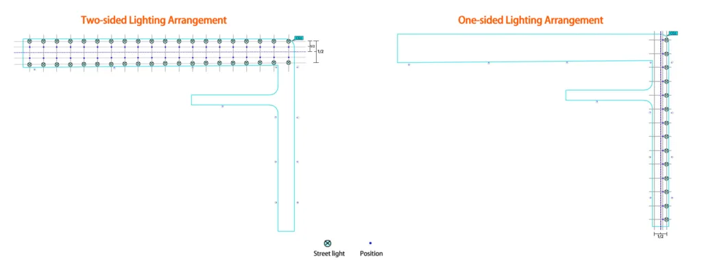
- single-sided, staggered, opposite, or center arrangement;
- fixture tilt and aiming direction;
- the required lighting target defined for the project.
If you still need to validate whether the chosen spacing and geometry make sense at design stage, use our Pole Height & Spacing for Solar Street Lights guide. This acceptance page assumes the design has already been approved and the installation is ready for field verification.
Step 2: Set out a practical on-site measurement grid
In field work, the most practical method is to test the roadway area between two adjacent poles and divide that area into repeatable grid cells. The center of each grid cell becomes the measurement point. This approach is easier to reproduce on site than trying to visually copy every software point from a screenshot, while still staying aligned with the design logic.
As a practical rule:
- take the road segment between two neighboring luminaires as one test zone;
- divide the road length into equal sections;
- divide the road width into equal bands across the carriageway;
- measure at the center point of each resulting cell.
| Measurement area size | Typical maximum point spacing |
|---|---|
| Up to 2.5 m | 0.5 m |
| More than 2.5 m and up to 6 m | 1.0 m |
| More than 6 m and up to 15 m | 2.0 m |
| More than 15 m and up to 50 m | 5.0 m |
| More than 50 m | 10.0 m |
Step 3: Measure illuminance correctly at every point
At each grid point, place the lux meter sensor horizontally at road-surface level and make sure the sensor is not shaded by the operator or nearby objects. Record each reading exactly as observed.
Good field practice includes:
- follow the same test sequence throughout the zone;
- avoid changing the dimming profile or operating mode during the test;
- note passing traffic, temporary ambient light, or unexpected obstruction if relevant;
- recheck any value that is obviously inconsistent with adjacent readings.
Step 4: Calculate average illuminance and overall uniformity
After recording all points, calculate the average illuminance and identify the minimum illuminance value.
Average illuminance: Eavg = (E1 + E2 + E3 + … + En) / n
Minimum illuminance: Emin = the lowest measured value in the grid
Overall uniformity: U0 = Emin / Eavg
Average lux alone does not describe actual night-use quality. A road can show acceptable average illuminance and still perform poorly if the spacing, optics, or aiming creates deep dark zones between poles. That is why overall uniformity should always be reviewed alongside average illuminance.
How to assess glare on site without turning this page into an optics-spec guide
This page keeps glare assessment practical and field-based. It does not attempt to replace a full optics selection guide. On site, the objective is to identify whether the installed fixture geometry creates obvious glare risk in actual viewing conditions.
Check the following items:
- whether the luminaire tilt angle matches the approved layout;
- whether pole height is consistent across the tested section;
- whether the beam appears to send excessive intensity into typical viewing angles;
- whether the lens or optical assembly was installed correctly;
- whether any field modification changed the intended light distribution.
If your team needs to define beam angle, CCT, CRI, or optical distribution requirements before ordering, use our separate CCT / CRI / Beam Angle for Solar Street Lights guide. That page handles specification logic; this page focuses only on field acceptance behavior after installation.
What to check when field results do not match the design report
If measured values differ from the approved design report, do not jump straight to the conclusion that the product failed. In many projects, the gap comes from geometry mismatch, operating-mode mismatch, or field-testing inconsistency.
- Measurement grid mismatch: Was the field grid laid out differently from the approved basis?
- Installation geometry mismatch: Are actual pole height, spacing, outreach, or tilt different from the drawing?
- Operating state mismatch: Was the system tested in the intended nighttime mode?
- Site condition mismatch: Are there obstructions, road-width differences, or reflective conditions not assumed in the design?
- Product configuration mismatch: Was the same optic, wattage, and fixture orientation actually installed?
If the issue starts much earlier in the workflow, such as questionable photometric files or unrealistic assumptions, review How to Read an IES File: 7 Red Flags for Fake Lumens before blaming the acceptance test itself.
Common causes of poor field acceptance
- pole spacing is too large for the installed optic;
- fixture tilt differs from the approved layout;
- mounting height in the field is different from the design assumption;
- the actual road width is wider than the design input;
- an unsuitable optical distribution was installed;
- the system is operating under a different dimming profile than expected.
Simple field acceptance checklist
| Checkpoint | Status |
|---|---|
| Approved design report available on site | Yes / No |
| Road geometry checked against design | Yes / No |
| Pole spacing and height confirmed | Yes / No |
| Lux meter calibration confirmed | Yes / No |
| Weather and pavement condition suitable | Yes / No |
| All field points recorded | Yes / No |
| Eavg calculated | Yes / No |
| Emin identified | Yes / No |
| Overall uniformity calculated | Yes / No |
| Glare-related installation checks completed | Yes / No |
| Measured results compared with approved design basis | Yes / No |
FAQ: Solar Street Light Acceptance Testing
What is the main purpose of solar street light acceptance testing?
The main purpose is to verify whether the installed lighting system performs on site as required, using real field measurements rather than brochure claims or nominal wattage.
What is the difference between commissioning and acceptance testing?
Commissioning checks whether the system is installed, configured, and operating correctly. Acceptance testing checks whether the installed system actually meets the required lighting-performance outcome on site.
How is overall uniformity calculated in a field test?
Overall uniformity is calculated as U0 = Emin / Eavg, where Emin is the minimum measured illuminance and Eavg is the average illuminance across all test points.
Why can field lux readings differ from the DIALux report?
Common reasons include grid mismatch, installation geometry differences, operating-mode differences, road-condition differences, or a mismatch between the approved design assumptions and the installed product configuration.
How should glare be checked during handover?
During handover, glare should be checked through practical field inspection of tilt, mounting height, aiming direction, and optical installation quality, unless the project specification requires a quantified glare metric.
Need help reviewing a solar street light project before final handover?
If you are preparing a municipal, EPC, industrial, or infrastructure project, Inlux Solar can support your team with lighting design alignment, system selection, and acceptance-oriented technical review before final sign-off.
Talk to Inlux Solar or explore our solar street light systems for project-specific support.