






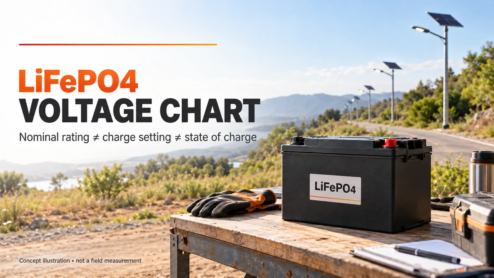
A LiFePO4 voltage chart starts with a 3.2 V nominal cell rating: 4 series groups give 12.8 V, 8 give 25.6 V, and 16 give 51.2 V. These are identification values—not charging instructions or a reliable percentage of charge remaining. For solar street lights, the useful question is whether the battery label, controller configuration and recorded operating voltage describe the same system.
Below is a reference for comparing battery offers and interpreting service records. It is not a procedure for opening a pack, changing protection thresholds or testing exposed terminals. Electrical measurements and configuration changes belong to qualified personnel following the exact product manual and site safety procedure.
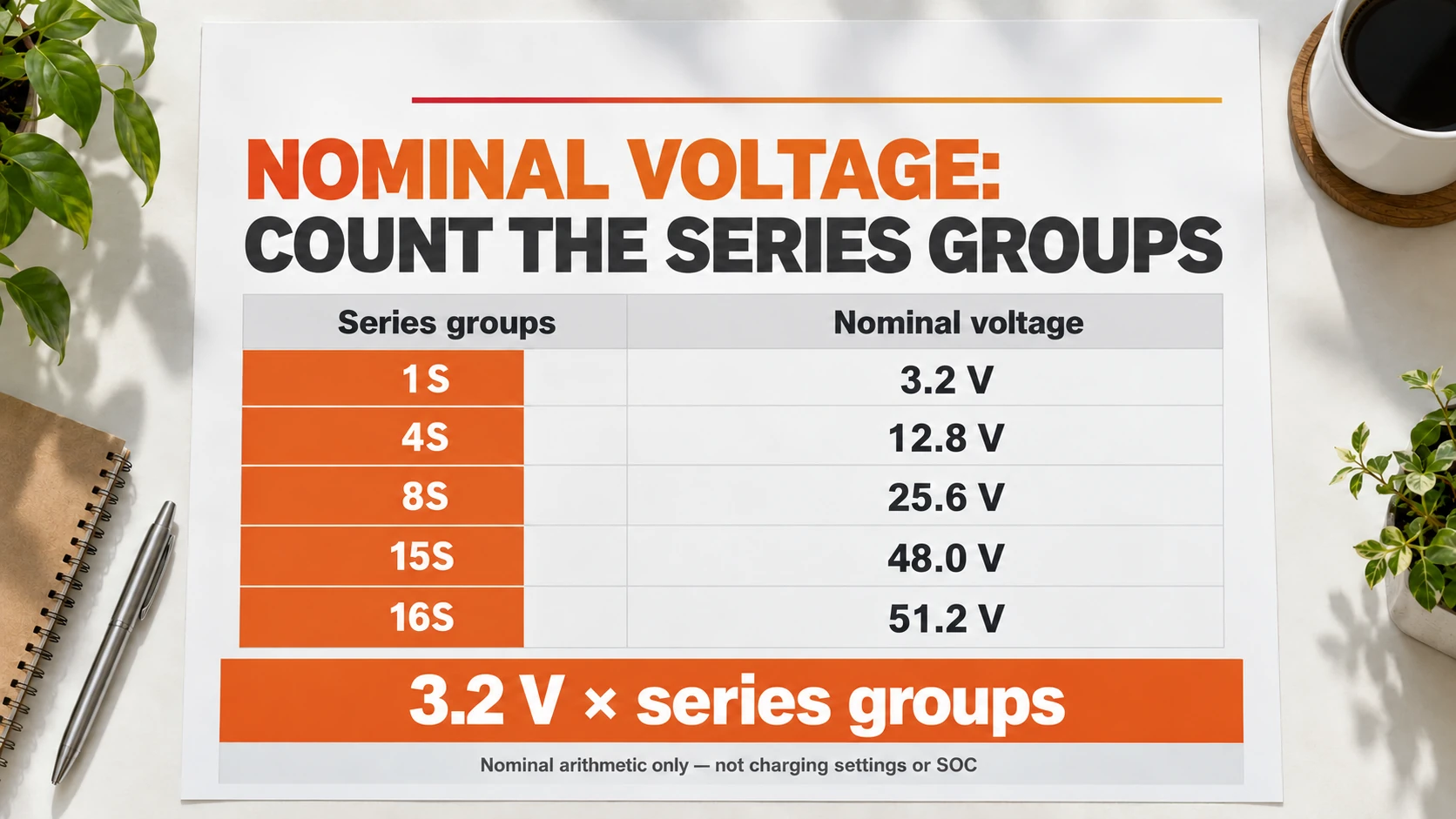
LiFePO4 voltage chart: nominal ratings by series count
| Series groups | Nominal arithmetic | Nominal pack rating |
|---|---|---|
| 1S | 1 × 3.2 V | 3.2 V |
| 4S | 4 × 3.2 V | 12.8 V |
| 8S | 8 × 3.2 V | 25.6 V |
| 15S | 15 × 3.2 V | 48.0 V |
| 16S | 16 × 3.2 V | 51.2 V |
The letter S describes groups in series. Parallel cells can increase capacity without increasing the nominal voltage of a series group. This table uses the common 3.2 V nominal LiFePO4 rating; it does not identify the internal configuration of an undocumented battery.
A listing that says “48 V lithium” is not enough to select a replacement. A 15S LiFePO4 pack is nominally 48.0 V, while a 16S pack is nominally 51.2 V. Both may appear in a broadly described 48 V product category, but that does not make their charging requirements interchangeable. Confirm the chemistry and exact series configuration in the supplier’s specification.
Keep other lithium chemistries out of this LiFePO4 voltage chart. Our comparison of LiFePO4 and other lithium-ion chemistries explains why “lithium” is not a complete battery specification. If the task is comparing stored energy rather than interpreting a reading, use the Ah-to-Wh conversion guide with the pack’s nominal rating.
Nominal voltage is not the charging setpoint
A charger normally needs a voltage above the battery’s nominal rating to charge it. The correct target comes from the approved battery and charging-system documentation—not from multiplying a value found in an unrelated online chart.
For a specific, checkable example, Victron’s Lithium Battery Smart technical data lists 12.8 V and 25.6 V nominal batteries and recommends charge voltages of 14.2 V and 28.4 V respectively. These values belong to the listed Victron products. They are not Inlux Solar settings, and they are not a universal prescription for LiFePO4 batteries.
That distinction matters when an offer includes only “12 V battery” and “lithium controller.” Ask the supplier to identify the approved charge profile for the quoted pack. A maximum cell limit, a controller target, a protection trip and a normal operating reading are four different quantities. Do not substitute one for another.
Read the voltage with its operating conditions
| Reading context | Record alongside the voltage | What the reading alone cannot establish |
|---|---|---|
| Resting | Time since charging or load removal; current; temperature | An exact charge percentage without a validated battery-specific method |
| Charging the specified battery | Charger stage, current and measurement point | Stored capacity or the next night’s lighting duration |
| Supplying the lamp | Lighting output setting, current and measurement point | Whether a lower reading is caused by charge level, load response or a connection issue |
A screenshot taken during midday charging and one taken during full lighting output are not a like-for-like battery comparison. Even the measurement point matters: a controller display and a battery-terminal measurement may not be reporting the same point in the circuit. Record where each value came from before deciding that two readings disagree.
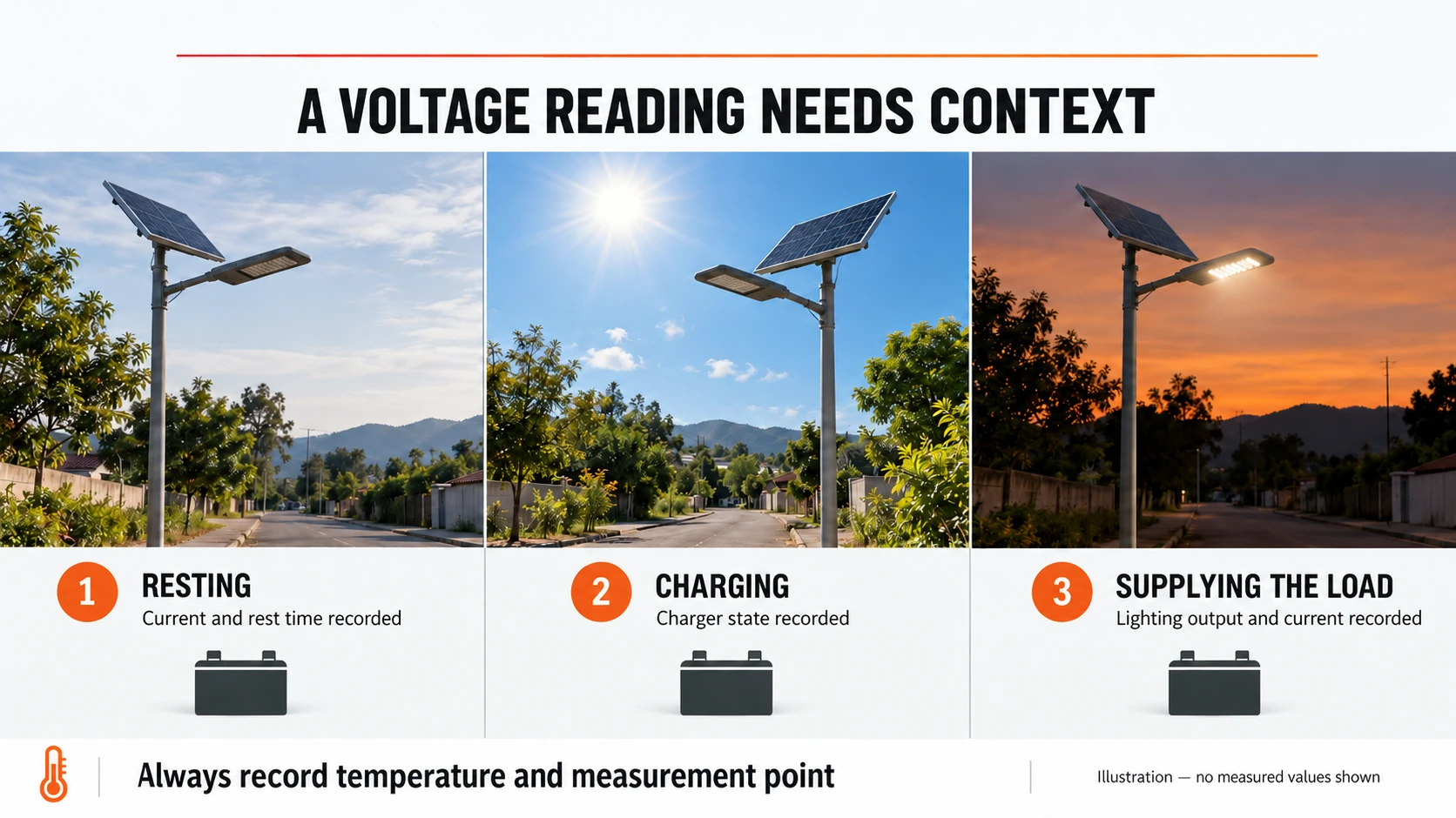
In a maintenance handover, a useful record says which pack was observed, at what time, under what lighting state, and by which monitoring method. “Battery reads 13.2 V” leaves those questions unanswered. Keep the record attached to the asset identifier so that a later technician does not compare different poles or replacement packs.
Why this LiFePO4 voltage chart does not assign SOC percentages
State of charge, or SOC, estimates the charge remaining. A voltage number by itself does not supply the battery-specific relationship, temperature, loading history or measurement conditions needed to turn that number into a defensible percentage. Treat a generic voltage-to-percentage table as an approximation with conditions, not a commissioning acceptance test.
The distinction is visible in Victron’s battery-monitoring guidance: its battery can report voltage and temperature, while SOC monitoring requires an appropriate BMS or separate battery monitor. The presence of a voltage display therefore does not prove that a system measures SOC.
For a solar-light quotation, ask how the displayed percentage is obtained and what is required to keep it valid. If a supplier provides an SOC chart, it should identify the battery model and the conditions under which it applies. A bare percentage column copied from another battery is not evidence that the offered light will meet its overnight schedule.
The same pack total can conceal different cell readings
Consider two hypothetical sets of four cell readings. In the first, 3.30 + 3.30 + 3.30 + 3.30 = 13.20 V. In the second, 3.50 + 3.30 + 3.25 + 3.15 = 13.20 V. The total is identical, but the individual readings are not.
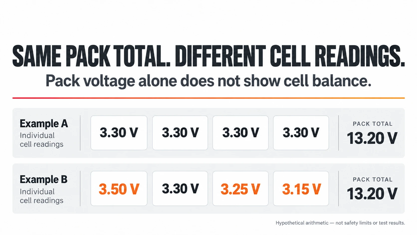
This is arithmetic, not a test result or a pass/fail limit. It explains why a total voltage cannot establish cell balance. Where the approved system provides cell-level diagnostics, qualified service personnel should interpret them against its documentation. Do not open a sealed lamp or bypass its BMS to obtain readings for an internet chart. The BMS battery guide covers the protection system separately.
Turn the chart into a better solar-light battery offer
Use the LiFePO4 voltage chart to resolve identity first, then compare the system. For an integrated All-in-One solar lighting system, request the battery specification for the exact integrated configuration; the enclosure’s appearance does not reveal the pack voltage. For an All-in-Two solar lighting configuration, a separate panel does not by itself identify the battery’s series count or charging profile.
| Battery-offer item | A useful answer from the supplier |
|---|---|
| Pack identity | Chemistry, exact battery model, revision and nominal voltage |
| Voltage compatibility | Approved controller profile and compatible operating range for that pack |
| Condition of a reported reading | Charging/resting/lighting state, time, temperature and measurement point |
| Charge-level evidence | SOC method and any model-specific conditions or calibration requirements |
| Lighting acceptance | Agreed operating schedule and battery-energy basis, not just a daytime voltage screenshot |
When reviewing a proposal for commercial parking lot lighting, a battery voltage is only one part of the record. It does not demonstrate that the lights maintained the required output through the agreed night. Keep voltage evidence separate from lighting-duration evidence; otherwise a healthy-looking daytime reading can answer the wrong procurement question.
If two offers disagree on the battery voltage, request clarification before comparing their prices. The supplier should explain whether they are alternative system designs or an unintended substitution. A corrected configuration description is more useful than another generic LiFePO4 voltage chart.
Frequently asked questions about LiFePO4 voltage charts
What voltage should a LiFePO4 battery be?
Start with its nominal rating and series count: commonly 3.2 V per series group, giving 12.8 V for 4S or 25.6 V for 8S. Its measured operating voltage will differ with conditions. The approved product specification—not the nominal number alone—defines the relevant limits.
Does 13.2 V mean a 12.8 V battery is nearly full?
Not reliably from that number alone. Confirm that the pack is LiFePO4, how and where the voltage was measured, and whether it was charging, resting or supplying a load. Use the battery-specific SOC method instead of assigning a universal percentage.
Is it okay to charge LiFePO4 to 100%?
Follow the manufacturer’s charging and storage instructions for the exact battery. A display reading of 100% is not permission to raise the charge voltage or hold the battery at a generic internet setpoint. Routine use, balancing and storage may have different requirements.
What is the ideal charging voltage for a 24 V LiFePO4 battery?
Confirm the actual pack configuration and its manual. A common nominal 25.6 V pack has 8 series groups, but this does not establish its approved charge profile. The manufacturer-specific example above illustrates why nominal voltage and charging voltage must be kept separate.
Are 48 V and 51.2 V LiFePO4 batteries interchangeable?
Not automatically. A 15S pack has a nominal 48.0 V rating and a 16S pack has a nominal 51.2 V rating. Compatibility also depends on the charger, load electronics, BMS and approved system configuration. Obtain written compatibility confirmation before substitution.
Can a LiFePO4 voltage chart prove solar-light backup time?
No. It cannot establish usable battery energy or the actual lighting schedule by itself. A backup-time claim needs a defined starting condition, operating profile and relevant performance evidence. Do not accept a single voltage screenshot as proof of several nights of autonomy.
Request the battery configuration with the lighting proposal
Inlux Solar’s standard warranty is 5 years; that is a commercial warranty term, not a voltage threshold or a guaranteed battery lifespan. When comparing commercial solar street-light configurations, send the project location, operating hours, quantity and any existing pack/controller identification. Request a configuration-specific quotation so the battery and lighting proposal can be evaluated together.